Which Geotechnical Sensor Is Best for Dam and Bridge Monitoring?
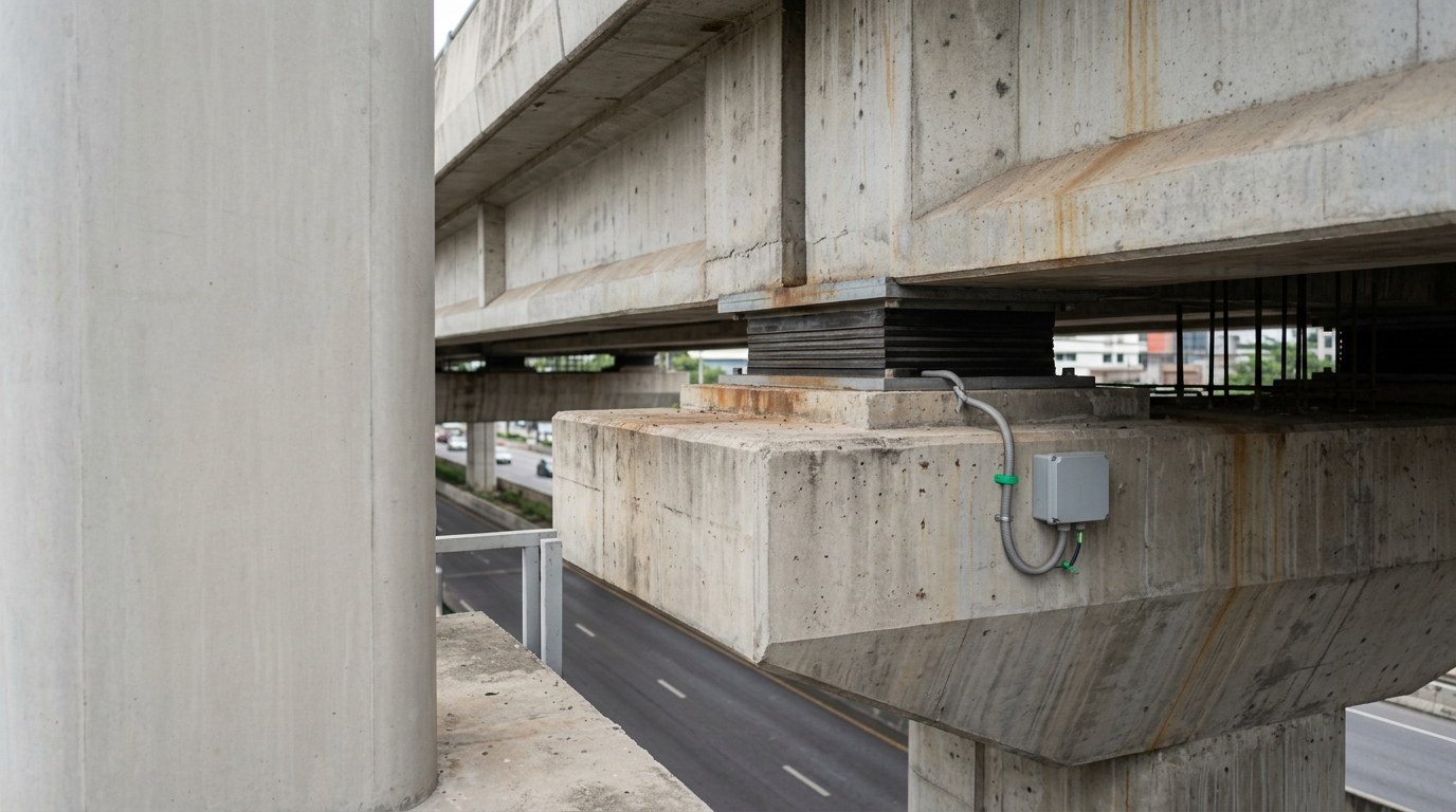
In August 2018, the Machchhu Dam failure in Morbi, Gujarat — one of India's deadliest dam disasters — demonstrated with brutal clarity what happens when structural warning systems are absent or inadequate. Decades later, the Dam Safety Act 2021 now mandates instrumentation and real-time monitoring for all large dams under CWC oversight, and IRC SP-35 sets out inspection and monitoring requirements for highway bridges. For procurement leads and consultants specifying sensor packages today, the question is no longer whether to instrument — it is which geotechnical sensor is best for dam and bridge monitoring given the structure type, loading regime, and data acquisition architecture in scope.
This guide provides a structured decision framework. It covers the principal sensor families used across dam and bridge applications, the physical parameters each measures, the Indian Standards that govern their deployment, and the project-level experience that informs sensor selection in Indian conditions. Whether you are specifying a vibrating-wire piezometer array for an earthen dam or a fibre-optic strain sensor network for a cable-stayed bridge, the selection logic follows the same engineering hierarchy: define the failure mode, identify the measurand, then match the sensor to the environment.
Key Takeaways
- Sensor selection must be driven by the dominant failure mode of the structure — seepage and pore pressure for earthen dams; strain, deflection, and dynamic response for bridges.
- The Dam Safety Act 2021 and CWC guidelines mandate instrumentation for all large dams; IRC SP-35 and IRC:114 govern bridge monitoring requirements in India.
- Vibrating-wire sensors remain the industry standard for long-term static monitoring in dam applications due to their frequency-based output and immunity to cable resistance drift.
- For long-span and cable-stayed bridges, fibre-optic and MEMS-based sensors provide the spatial resolution and dynamic bandwidth that conventional point sensors cannot match.
- Wireless DAQ architectures — as deployed by Geolook for Neeladari Buildtech's Bridge Health Monitoring System — reduce installation cost and enable remote data retrieval in inaccessible locations.
What Is Geotechnical Sensor Selection for Dam and Bridge Monitoring?
Geotechnical sensor selection for dam and bridge monitoring is the engineering process of matching measurement instruments to the specific physical parameters — pore pressure, strain, displacement, acceleration, or crack width — that govern the safety and serviceability of a structure, based on its material type, loading conditions, environmental exposure, and required data resolution.
This definition matters because procurement teams sometimes treat sensor selection as a catalogue exercise. It is not. A vibrating-wire piezometer installed at the wrong depth in a zoned earthen dam provides misleading phreatic surface data. A uniaxial accelerometer placed at the mid-span of a cable-stayed bridge misses torsional modes that are critical to flutter assessment under IS 1893 Part 3 loading. The measurand must be defined before the sensor is specified.
Explore the full range of geotechnical and structural sensors available from Geolook to understand the instrumentation families discussed in this guide.
Dam Sensor Selection: Parameters, Instruments, and Standards
Dam safety monitoring under CWC guidelines and IS 7894 (Code of Practice for Stability Analysis of Earth Dams) requires continuous or periodic measurement of five primary parameters: pore water pressure, seepage flow, settlement and deformation, crack development, and seismic response. Each parameter demands a different instrument family.
Pore Water Pressure: Vibrating-wire piezometers (VWP) are the standard instrument for measuring pore pressure in embankment dams and foundations. They output a frequency signal in Hz, which is converted to pressure in kPa. Because the output is frequency-based rather than voltage-based, VWPs are immune to cable resistance changes over long cable runs — a critical advantage in dams where instrument cables may run 200–500 metres to a data logger. Standpipe piezometers remain acceptable for slow-response applications but are unsuitable for real-time automated monitoring.
Seepage and Leakage: V-notch weirs with pressure transducers or electromagnetic flow meters measure seepage discharge in litres per second. An increase in seepage volume, particularly if accompanied by turbidity, is a primary indicator of internal erosion — the failure mechanism responsible for a significant proportion of embankment dam failures globally (ICOLD Bulletin 164, 2015).
Settlement and Deformation: Hydraulic settlement gauges, borehole extensometers, and surface survey monuments (monitored by total station or GNSS) track vertical and horizontal movement. IS 1892 (Site Investigation for Foundations) provides the geotechnical baseline against which deformation readings are interpreted. Inclinometers — either in-place servo-accelerometer type or manual probe type — measure lateral deformation profiles in embankment slopes and abutments.
Seismic Response: Strong-motion accelerometers conforming to IS 1893 Part 1 requirements are installed at the dam crest, mid-height, and foundation to record peak ground acceleration (PGA) in mm/s² and to trigger alert protocols when thresholds are exceeded.
For a complete dam instrumentation specification, refer to Geolook's dam monitoring sensor and DAQ systems.
Bridge Sensor Guide: Matching Instruments to Bridge Typology
Bridge monitoring under IRC SP-35, IRC:6 (Loads and Load Combinations), and IRC:114 (Guidelines for Structural Health Monitoring of Bridges) requires a sensor strategy that reflects the bridge's structural form. A simply supported prestressed concrete girder bridge on NH-44 has fundamentally different monitoring requirements from a cable-stayed bridge on a railway corridor. The bridge sensor guide below organises instrument selection by structural typology.
Prestressed Concrete Girder Bridges: Vibrating-wire strain gauges embedded in or surface-mounted on girders measure micro-strain (µε) under live load. Crack meters monitor crack width in millimetres at critical sections. Tiltmeters at pier caps detect differential settlement. IRC:112 (Code of Practice for Concrete Road Bridges) provides the design strain limits against which sensor thresholds are calibrated.
Cable-Stayed and Extra-Dosed Bridges: Stay cable force monitoring using vibrating-wire load cells or frequency-based tension measurement (from accelerometers measuring cable vibration frequency in Hz) is essential. Sandeep Gupta, IRSE, former Chief Administrative Officer of Indian Railways and Strategic Advisor at Geolook, brings direct domain expertise in cable-stayed and extra-dosed bridge engineering — a typology where cable tension drift of even 5–8% from design values can indicate anchorage distress requiring immediate inspection. Fibre Bragg Grating (FBG) sensors provide distributed strain measurement along stay cables and deck sections with spatial resolution down to 1 metre.
Steel Truss and Arch Bridges: Fatigue monitoring using high-frequency strain gauges (sampling at 100–1000 Hz) captures stress cycles at welded connections. IS 1893 Part 3 governs seismic demand on bridges; accelerometers at deck and pier levels record dynamic response in three axes.
Foundation and Substructure: Vibrating-wire earth pressure cells at pile caps and abutments measure contact pressure in kPa. Borehole inclinometers in approach embankments detect lateral movement that precedes abutment rotation. IRC:78 (Standard Specifications and Code of Practice for Road Bridges — Foundations and Substructure) sets the geotechnical design basis for these measurements.
IIT-Mandi's Bridge Health Monitoring programme, for which Geolook supplied monitoring accessories, demonstrates the academic rigour now being applied to bridge instrumentation in India's seismically active zones. Similarly, RITES Ltd engaged Geolook to develop a 3D Digital Twin and VR Visualization Platform for a Bridge Health Monitoring System — an integration that allows sensor data to be visualised spatially against the bridge's structural model in real time.
For a detailed overview of bridge-specific instrumentation packages, see Geolook's bridge monitoring sensor systems and DAQ solutions.
Sensor Performance Comparison: Dam and Bridge Applications
The table below provides a structured comparison of the principal sensor types used in dam and bridge monitoring, covering measurand, output signal, typical range, accuracy class, and primary application context. This matrix supports dam sensor selection and bridge sensor guide decisions at the specification stage.
| Sensor Type | Measurand | Output Signal | Typical Range | Accuracy Class | Primary Application |
|---|---|---|---|---|---|
| Vibrating-Wire Piezometer | Pore water pressure | Frequency (Hz) | 0–700 kPa | ±0.1% FS | Earthen dams, bridge foundations |
| Vibrating-Wire Strain Gauge | Structural strain | Frequency (Hz) | ±3000 µε | ±0.5% FS | Concrete girders, piers, dam galleries |
| MEMS Accelerometer | Acceleration / vibration | Voltage / digital | ±2g to ±10g | ±1% FS | Bridge deck dynamics, seismic response |
| Fibre Bragg Grating (FBG) | Distributed strain / temperature | Wavelength shift (nm) | ±5000 µε | ±1 µε | Cable-stayed bridges, long-span decks |
| In-Place Inclinometer | Lateral deformation | Voltage / digital | ±30° (±53 mm/m) | ±0.01° | Dam embankment slopes, bridge abutments |
| Vibrating-Wire Load Cell | Axial force | Frequency (Hz) | 0–5000 kN | ±0.1% FS | Stay cable anchorages, bearing loads |
| Crack Meter (VW type) | Crack / joint displacement | Frequency (Hz) | 0–50 mm | ±0.1% FS | Concrete dam faces, bridge deck joints |
| Strong-Motion Accelerometer | Peak ground acceleration | Voltage / digital | ±2g | ±0.5% FS | Dam crest, bridge piers (IS 1893 compliance) |
Wireless DAQ and Data Transmission Architecture
Sensor selection cannot be separated from data acquisition architecture. A technically correct sensor installed with an inadequate DAQ system produces unreliable or incomplete data. In remote dam and bridge locations — common across India's highway and irrigation infrastructure — wired DAQ systems face challenges of cable length, vandalism, and maintenance access.
Wireless DAQ systems using LoRaWAN, 4G LTE, or satellite backhaul address these constraints. Neeladari Buildtech's Bridge Health Monitoring System, instrumented with Geolook's wireless DAQ, demonstrates that wireless architectures can achieve data latency under 60 seconds for alert-critical parameters while eliminating the cable management burden on structures with complex geometry.
Key DAQ specifications to evaluate during procurement include: sampling rate (Hz) per channel, number of simultaneous channels, onboard data storage capacity (days of autonomous operation), power supply options (solar, mains, or battery), and communication protocol compatibility with the project's central monitoring platform. For bridges on national highways, NHAI's SHM framework increasingly requires data to be accessible via a web-based dashboard with configurable alert thresholds — a requirement that must be reflected in the DAQ specification from the outset.
For transport infrastructure projects, Geolook's structural health monitoring solutions for transport infrastructure cover both highway and railway bridge applications.
Procurement Checklist: Evaluating Sensor Packages for Dam and Bridge Projects
Procurement leads evaluating sensor packages for dam or bridge monitoring should apply the following criteria systematically. These criteria reflect the requirements of the Dam Safety Act 2021, CWC instrumentation guidelines, IRC:114, and standard EPC contract quality plans.
- Failure Mode Coverage: Does the sensor suite address all critical failure modes identified in the structural safety assessment? For earthen dams, this means pore pressure, seepage, and deformation. For bridges, this means strain, deflection, dynamic response, and — for prestressed structures — tendon force loss.
- Environmental Compatibility: Are sensors rated for the site's temperature range, humidity, and chemical exposure? Vibrating-wire sensors are generally rated to operate between −20°C and +80°C and are suitable for submerged installation. FBG sensors require hermetic packaging in high-humidity environments.
- Long-Term Stability: What is the sensor's stated zero drift over a 10-year period? For dam monitoring, where instruments may remain in service for 20–50 years, long-term stability is more important than initial accuracy.
- Calibration Traceability: Are calibration certificates traceable to NABL-accredited laboratories? IS 13311 and IS 516 require calibration traceability for instruments used in structural assessment.
- Integration with Digital Twin Platforms: Can sensor outputs be ingested by a 3D digital twin or BIM-linked monitoring platform? RITES Ltd's engagement with Geolook for a 3D Digital Twin and VR Visualization Platform for Bridge Health Monitoring demonstrates that this integration is now a live procurement requirement for PSU clients.
- Supplier Experience in Indian Conditions: Has the supplier demonstrated deployment experience in India's seismic zones, monsoon conditions, and remote access environments? Project references from IIT-Mandi, RITES, and Neeladari Buildtech provide verifiable evidence of this capability.
For further technical guidance on bridge-specific monitoring strategies, read our detailed post on bridge structural monitoring instrumentation and data interpretation.
Regulatory and Standards Framework for Dam and Bridge Sensor Deployment in India
Understanding the regulatory framework is essential for procurement leads who must ensure that sensor specifications satisfy statutory obligations, not merely technical preferences.
Dam Safety Act 2021: Enacted by the Government of India, this Act mandates that all specified dams maintain an instrumentation and monitoring system. The National Committee on Dam Safety (NCDS) and State Dam Safety Organisations (SDSOs) are empowered to direct dam owners to install or upgrade instrumentation. CWC's Dam Rehabilitation and Improvement Project (DRIP) guidelines provide detailed instrumentation schedules for different dam types.
IS 7894:1975 (Reaffirmed 2018): Code of Practice for Stability Analysis of Earth Dams — provides the geotechnical framework within which piezometer and inclinometer data is interpreted.
IRC:114:2021: Guidelines for Structural Health Monitoring of Bridges — the primary Indian standard governing bridge SHM. It specifies sensor types, data acquisition requirements, alert threshold methodology, and reporting obligations for bridges on national and state highways.
IRC SP-35: Guidelines for Inspection and Maintenance of Bridges — mandates periodic inspection and, for critical bridges, continuous monitoring.
IS 1893 Part 1 and Part 3: Criteria for Earthquake Resistant Design of Structures — governs seismic instrumentation requirements for dams and bridges in Zones III, IV, and V, which cover a substantial portion of India's infrastructure corridor.
To understand how these standards apply to real-time monitoring deployments on national highways, see our post on how does bridge health monitoring work for national highways in india.
For a broader view of sensor technology options deployed across Indian bridge projects, the post on real time bridge monitoring sensors india provides additional context on sensor selection in live traffic environments.
Frequently Asked Questions
Q: Which geotechnical sensor is best for dam and bridge monitoring when budget is constrained?
A: Vibrating-wire piezometers and vibrating-wire strain gauges offer the best balance of long-term stability, low maintenance, and cost-effectiveness for constrained budgets. Their frequency-based output eliminates signal drift over long cable runs, reducing recalibration costs. For dams, prioritise pore pressure and seepage monitoring; for bridges, prioritise strain at critical sections and deflection at mid-span.
Q: What is the difference between a vibrating-wire sensor and a MEMS sensor for bridge monitoring?
A: A vibrating-wire sensor measures quasi-static parameters such as strain, pressure, and load by detecting the resonant frequency of a tensioned wire, making it ideal for long-term structural monitoring with minimal drift. A MEMS sensor measures dynamic parameters such as acceleration and vibration at high sampling rates (up to 1000 Hz), making it suited for modal analysis, traffic-induced vibration, and seismic response monitoring on bridges.
Q: Does the Dam Safety Act 2021 specify which sensors must be installed?
A: The Dam Safety Act 2021 mandates instrumentation and monitoring for all specified dams but delegates detailed instrumentation schedules to CWC guidelines and State Dam Safety Organisations. CWC's DRIP guidelines specify minimum instrumentation including piezometers, seepage measurement, settlement monuments, and strong-motion accelerometers for dams in seismic zones III and above under IS 1893.
Q: How are sensor alert thresholds set for bridge monitoring under IRC:114?
A: IRC:114:2021 requires alert thresholds to be established through a combination of design analysis, baseline monitoring data collected during the initial commissioning period, and structural assessment by a qualified engineer. Thresholds are typically set at three levels — advisory, alert, and alarm — corresponding to increasing levels of deviation from baseline strain, deflection, or vibration values in µε, mm, or mm/s² respectively.
Q: Can wireless DAQ systems meet the data reliability requirements for dam safety monitoring?
A: Wireless DAQ systems can meet dam safety monitoring reliability requirements when designed with redundant communication paths, onboard data storage for a minimum of 30 days of autonomous operation, and tamper-evident enclosures rated to IP67 or higher. CWC guidelines require continuous data availability for critical parameters; wireless systems using 4G LTE with satellite backup have demonstrated compliance in remote dam sites across India.
Request consultation
Selecting the right sensor package for a dam or bridge project requires matching instrument specifications to failure modes, regulatory obligations, and data acquisition architecture — not simply choosing the lowest-cost item on a schedule of rates. Geolook's instrumentation team has supplied and integrated monitoring systems for IIT-Mandi's Bridge Health Monitoring programme, RITES Ltd's 3D Digital Twin and VR Visualization Platform for Bridge Health Monitoring, and Neeladari Buildtech's Wireless DAQ for Bridge Health Monitoring System.
If you are at the specification or procurement stage for a dam or bridge monitoring project, our engineers can review your structural assessment, identify the critical measurands, and recommend a sensor and DAQ package that satisfies CWC, IRC:114, and IS 1893 requirements.
Request a technical consultation with Geolook's SHM instrumentation team to discuss your project requirements, or download the full dam and bridge sensor selection guide at the asset slug: which-geotechnical-sensor-is-best-for-dam-and-bridge-monitoring-guide.
Project inquiry
Talk to a Geolook™ specialist
Share your monitoring requirement and our team will help identify the right next step.
By submitting, you agree that Geolook™ may contact you about this inquiry. Your details are not added to a marketing list.