What Geotechnical Instruments Are Essential for Dam Safety Monitoring?
In August 2018, the Cheruthoni dam in Kerala's Idukki reservoir complex released floodgates for the first time in 26 years, displacing over a million people downstream — a crisis that underscored how inadequate real-time instrumentation leaves dam operators reacting to emergencies rather than anticipating them. Understanding what geotechnical instruments are essential for dam safety monitoring systems is not an academic exercise; it is a statutory obligation under India's Dam Safety Act 2021, which mandates instrumentation, regular inspection, and emergency action plans for all specified dams. The Central Water Commission (CWC) estimates India has over 5,200 large dams, many of which were constructed before modern monitoring standards existed. For consulting engineers and students entering this field, a clear, instrument-by-instrument understanding of dam safety monitoring is the foundation of every safe design and every defensible inspection report.
Key Takeaways
- The Dam Safety Act 2021 and CWC guidelines legally mandate instrumentation for all large dams in India; IS 7894 provides the technical framework for embankment dam safety.
- Core instruments include vibrating wire piezometers, inclinometers, settlement gauges, seepage measurement weirs, and strong-motion accelerographs — each measuring a distinct failure mode.
- A complete dam sensors list covers pore water pressure, deformation, seepage, stress, and seismic response; no single instrument covers all failure modes.
- Vibrating wire (VW) transducers dominate dam monitoring because their frequency-based output is immune to long cable resistance errors over the multi-kilometre distances typical in dam installations.
- Automated data acquisition systems (ADAS) connected to a SCADA or cloud dashboard convert raw sensor readings into actionable threshold alerts, reducing the risk of human-error-driven missed alarms.
What Geotechnical Instruments Are Essential for Dam Safety Monitoring Systems
Geotechnical instruments for dam safety monitoring are devices embedded in or installed on a dam structure and its foundation to continuously or periodically measure physical parameters — pore water pressure, deformation, seepage, stress, and ground motion — that indicate the structural condition of the dam.
The Dam Safety Act 2021 classifies dams by hazard potential (High, Medium, Low) and requires that High and Medium hazard dams maintain functional instrumentation at all times. CWC's Guidelines for Instrumentation of Dams and IS 7894:1975 (Code of Practice for Safety of Earth and Rockfill Dams) together define the minimum instrument suite. For a consulting engineer preparing a dam instrumentation plan, the starting point is always a failure mode analysis: seepage-induced piping, slope instability, foundation uplift, and earthquake-induced liquefaction each demand a different sensor type.
Explore the full range of dam monitoring instruments and systems available from Geolook to match each failure mode with the appropriate transducer technology.
Piezometers: Measuring Pore Water Pressure in Embankments and Foundations
The piezometer is the single most critical instrument in any dam sensors list. Elevated pore water pressure within an embankment or its foundation reduces effective stress, directly lowering the factor of safety against slope failure and piping. IS 7894 recommends piezometer installation at the upstream shell, core, downstream shell, and foundation of every earth and rockfill dam.
Vibrating wire piezometers are the industry standard for permanent dam installations. A tensioned steel wire inside a sealed housing vibrates at a frequency proportional to the applied water pressure. Because the output is a frequency (typically 400–1200 Hz range), it is unaffected by cable resistance changes caused by moisture ingress over long cable runs — a critical advantage in dam galleries that may extend hundreds of metres. Full-scale ranges commonly used in dam cores are 0–350 kPa and 0–700 kPa, with resolution better than 0.025% FS.
Standpipe (Casagrande) piezometers remain in use for periodic manual readings where real-time data is not required, but they cannot feed automated alarm systems. For high-hazard dams, the CWC recommends vibrating wire piezometers connected to automated data loggers with telemetry.
For a detailed technical breakdown, read about the vibrating wire piezometer working principle and how frequency-output transducers maintain accuracy over long cable runs in dam galleries.
Understanding real time pore water pressure monitoring in dams is essential for engineers designing automated threshold-alert systems that comply with Dam Safety Act 2021 requirements.
Inclinometers: Tracking Lateral Deformation in Dam Slopes and Foundations
An inclinometer dam installation measures lateral displacement of the embankment or foundation by tracking the tilt of a grouted casing installed vertically through the dam body. Readings are taken at 0.5 m intervals from casing bottom to top, producing a displacement profile that reveals whether the dam is deforming uniformly or developing a shear zone at a specific depth.
In-place inclinometers (IPIs) use a chain of biaxial MEMS or vibrating wire tilt sensors permanently installed inside the casing, enabling continuous automated monitoring. Manual inclinometer probes, which are lowered into the casing periodically, are used for baseline surveys and periodic inspections. Typical measurement range is ±30° with resolution of 0.01 mm per 500 mm gauge length.
For embankment dams on weak alluvial foundations — common in the Indo-Gangetic plain — inclinometer data is often the earliest indicator of foundation creep. CWC guidelines recommend inclinometer casings at the dam centreline and at the downstream toe for all High hazard dams exceeding 30 m height.
Settlement and Deformation Monitoring: Surface and Subsurface Instruments
Vertical deformation of the dam crest and embankment is monitored using a combination of surface and subsurface instruments. Surface settlement is measured by precise geodetic levelling of benchmark monuments on the dam crest and downstream berm, typically to an accuracy of ±1 mm using digital levels. IS 7894 recommends crest settlement monuments at intervals not exceeding 50 m.
Settlement plates and hydraulic settlement gauges measure subsurface compression within the embankment fill layers. A hydraulic settlement gauge consists of a liquid-filled tube connecting a settlement point buried in the fill to a readout panel in the inspection gallery; differential head readings convert directly to settlement in millimetres.
Multipoint borehole extensometers (MPBXs) measure relative displacement between anchor points at different depths in the foundation rock, identifying zones of differential compression or heave. In concrete gravity dams, plumb lines (direct and inverted) suspended in inspection galleries measure horizontal displacement of the dam body relative to its foundation, with reading accuracy of ±0.1 mm using optical micrometers.
Seepage Measurement: Weirs, Flow Meters, and Turbidity Sensors
Seepage through and beneath a dam is normal and expected; uncontrolled or increasing seepage carrying fine particles (internal erosion) is a precursor to piping failure. The dam sensors list for seepage monitoring includes V-notch or rectangular weirs in the inspection gallery drain sumps, calibrated to measure flow in litres per second. A sudden increase in seepage rate — particularly if accompanied by turbidity — is a Category 1 alert under CWC emergency action plan protocols.
Automated seepage monitoring uses electromagnetic flow meters or ultrasonic flow meters installed in gallery drains, with data transmitted to the SCADA system. Turbidity sensors (nephelometers) measure suspended sediment concentration in mg/L; a rising turbidity trend at constant seepage flow indicates particle migration and potential piping initiation.
For concrete dams, uplift pressure beneath the base slab is measured by piezometers installed in drain holes drilled into the foundation rock. Uplift pressure directly reduces the stabilising weight in the overturning and sliding stability calculations governed by IS 6512:1984 (Criteria for Design of Solid Gravity Dams).
Stress and Strain Monitoring in Concrete Dams
Concrete gravity and arch dams require monitoring of internal stress and strain to detect cracking, thermal gradients, and load redistribution. Vibrating wire strain gauges embedded in concrete during construction measure micro-strain (με) changes; typical dam concrete gauges have a range of ±3000 με with resolution of 1 με. Paired with a thermistor in the same housing, they allow temperature-corrected stress calculations using the concrete's elastic modulus.
Carlson stress meters and no-stress strain gauges are used to separate thermally induced strain from mechanically induced strain — a distinction critical for arch dams where seasonal temperature swings of 20–30°C can generate significant apparent strain signals.
Joint meters (crack meters) installed across construction joints and contraction joints in concrete dams measure joint opening and closing in millimetres, providing direct evidence of whether the dam monoliths are behaving as designed or experiencing differential movement. For hydropower dams, penstock strain gauges monitor hoop stress in steel penstocks under operating pressure, typically 5–20 MPa depending on head.
Learn how vibrating wire strain gauges compare to MEMS sensors for dam monitoring in India to select the right transducer technology for your specific dam type and monitoring duration.
Seismic Monitoring: Strong-Motion Accelerographs
India's dam inventory includes structures in Seismic Zones III, IV, and V as defined by IS 1893 (Part 1):2016. The Dam Safety Act 2021 requires that all High hazard dams in Zones III and above be equipped with strong-motion accelerographs (SMAs) to record earthquake ground motion. SMAs measure acceleration in mm/s² (or g) in three orthogonal axes; typical dam-grade instruments have a full-scale range of ±2g with a flat frequency response from DC to 80 Hz.
Post-earthquake inspection protocols require comparison of recorded peak ground acceleration (PGA) against the dam's design basis earthquake (DBE) and maximum credible earthquake (MCE) levels. If recorded PGA exceeds 50% of the DBE value, a detailed structural inspection is mandatory before the reservoir is returned to full supply level. Accelerograph data also feeds into finite element model updating for dams with digital twin platforms.
Instrument-Application Matrix for Dam Safety Monitoring
The table below maps each instrument category to its measured parameter, applicable dam type, relevant Indian Standard or guideline, and typical specification range. This matrix directly answers what geotechnical instruments are essential for dam safety monitoring systems for a given dam type and failure mode.
| Instrument | Measured Parameter | Dam Type | Indian Standard / Guideline | Typical Specification |
|---|---|---|---|---|
| Vibrating Wire Piezometer | Pore water pressure (kPa) | Earth, Rockfill | IS 7894, CWC Instrumentation Guidelines | 0–700 kPa, resolution <0.025% FS |
| In-Place Inclinometer (IPI) | Lateral displacement (mm) | Earth, Rockfill, Foundation | IS 7894, CWC Guidelines | ±30°, resolution 0.01 mm/500 mm |
| Settlement Plate / Hydraulic Gauge | Vertical deformation (mm) | Earth, Rockfill | IS 7894 | ±300 mm range, ±1 mm accuracy |
| V-Notch Weir / Flow Meter | Seepage flow (L/s) | All dam types | CWC Emergency Action Plan Protocol | 0.01–100 L/s, ±2% accuracy |
| Turbidity Sensor (Nephelometer) | Suspended sediment (mg/L) | All dam types | CWC Guidelines | 0–1000 NTU, ±2% FS |
| Vibrating Wire Strain Gauge | Micro-strain (με) | Concrete Gravity, Arch | IS 6512, IS 13311 | ±3000 με, resolution 1 με |
| Joint Meter (Crack Meter) | Joint opening/closing (mm) | Concrete Gravity, Arch | IS 6512 | ±25 mm, resolution 0.025 mm |
| Strong-Motion Accelerograph | Ground acceleration (g) | All dam types in Zones III–V | IS 1893 (Part 1):2016, Dam Safety Act 2021 | ±2g, DC–80 Hz flat response |
| Plumb Line (Direct/Inverted) | Horizontal displacement (mm) | Concrete Gravity, Arch | IS 6512 | ±150 mm range, ±0.1 mm reading accuracy |
| Multipoint Borehole Extensometer | Foundation rock displacement (mm) | Concrete, Rockfill on rock | IS 7894, CWC Guidelines | ±50 mm per anchor, resolution 0.01 mm |
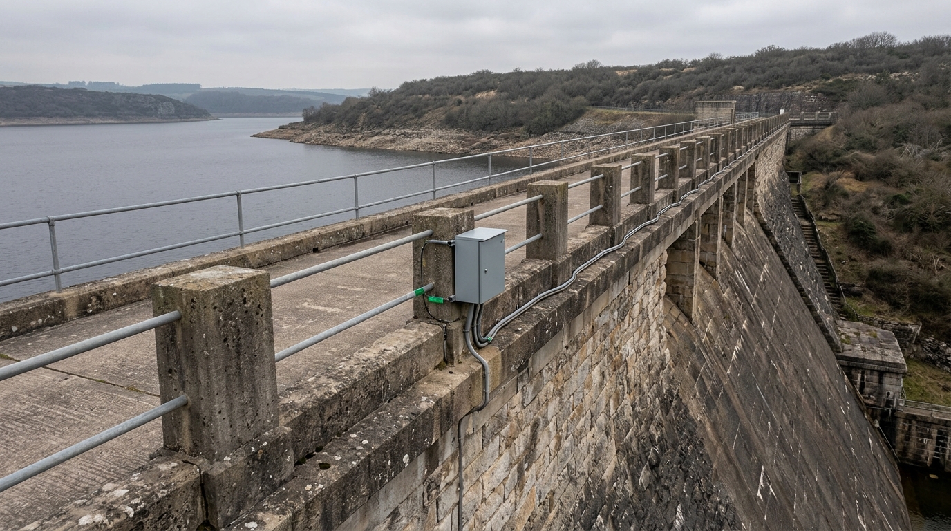
Data Acquisition and Telemetry: Connecting Instruments to Decision-Makers
Individual sensors generate value only when their data reaches engineers who can act on it. Automated data acquisition systems (ADAS) for dams typically use multiplexed vibrating wire readout modules that can address 16–64 channels per unit, scanning each sensor at programmable intervals from 1 minute to 24 hours depending on hazard level and reservoir condition.
For High hazard dams, CWC recommends continuous scanning with GSM/GPRS or satellite telemetry to a central dam safety control room. Data is compared against threshold values — typically set at 80% of design pore pressure, 50 mm of unexpected crest settlement, or 2 L/s increase in gallery seepage — and automated SMS or email alerts are dispatched when thresholds are breached.
Solar-powered remote terminal units (RTUs) are standard for dams in remote catchments where grid power is unreliable. Battery backup of 72 hours minimum is recommended to maintain data continuity during flood events when dam safety data is most critical. Explore Geolook's full sensor portfolio for structural and geotechnical monitoring to understand how VW transducers, MEMS sensors, and DAQ hardware integrate into a complete dam ADAS.
For hydropower and irrigation dam projects, Geolook's energy sector monitoring solutions cover the full instrumentation lifecycle from sensor selection through SCADA integration.
Frequently Asked Questions
Q: What is a piezometer and why is it the most important instrument in dam safety monitoring?
A: A piezometer is a pressure transducer installed in the embankment or foundation of a dam to measure pore water pressure in kPa. It is the most critical dam safety instrument because elevated pore pressure directly reduces the effective stress and factor of safety against slope failure and piping — the two most common causes of embankment dam failure. IS 7894 mandates piezometer installation at multiple zones in every earth and rockfill dam.
Q: What does an inclinometer measure in a dam installation?
A: An inclinometer dam installation measures the lateral displacement profile of the embankment or foundation by tracking the tilt of a grouted casing at 0.5 m depth intervals. It identifies shear zones, slope creep, and foundation movement that surface surveys cannot detect. In-place inclinometers provide continuous automated data; manual probes are used for periodic baseline surveys and inspections.
Q: What is the minimum dam sensors list required under the Dam Safety Act 2021?
A: The Dam Safety Act 2021, read with CWC instrumentation guidelines, requires High hazard dams to maintain piezometers, settlement monuments, seepage measurement devices, and strong-motion accelerographs (in seismic zones). IS 7894 additionally specifies inclinometers and foundation drainage monitoring. The exact dam sensors list varies by dam type, height, hazard classification, and seismic zone designation under IS 1893.
Q: Why are vibrating wire sensors preferred over electrical resistance sensors for dam monitoring?
A: Vibrating wire sensors are preferred for dam monitoring because their frequency-based output is immune to cable resistance changes caused by moisture, temperature variation, and long cable runs — conditions inherent in dam galleries extending hundreds of metres. Electrical resistance (strain gauge) sensors are susceptible to zero drift over multi-year deployments, making them less reliable for the 50–100 year service life typical of dam instrumentation systems.
Q: How often should dam instrumentation readings be taken according to CWC guidelines?
A: CWC guidelines recommend manual reading frequencies of weekly during first filling, monthly during normal operation, and daily during flood or seismic events for High hazard dams. Automated ADAS systems should scan continuously with intervals of 15–60 minutes during normal conditions and 1–5 minutes during alert conditions. The Dam Safety Act 2021 requires that instrumentation data be submitted to the State Dam Safety Organisation (SDSO) at prescribed intervals.
Compare dam instruments
Selecting the right instrument suite for a dam safety monitoring system requires matching each sensor type to the specific failure mode, dam type, and data acquisition strategy relevant to your project. Whether you are specifying instruments for a new High hazard embankment dam, retrofitting an ageing concrete gravity structure, or preparing an instrumentation plan for CWC or SDSO submission, Geolook's engineering team can support sensor selection, installation design, and ADAS integration.
For a comprehensive overview of dam safety monitoring practices in India — including inspection protocols, threshold setting, and emergency action plan requirements under the Dam Safety Act 2021 — visit our detailed technical guide.
Review the complete dam monitoring instrument range including vibrating wire piezometers, in-place inclinometers, settlement gauges, seepage flow meters, and strong-motion accelerographs, with full technical specifications and installation guidance.
To discuss your specific dam instrumentation requirements or request a technical proposal, contact Geolook's dam safety instrumentation team.