How Does Bridge Health Monitoring Work for National Highways in India
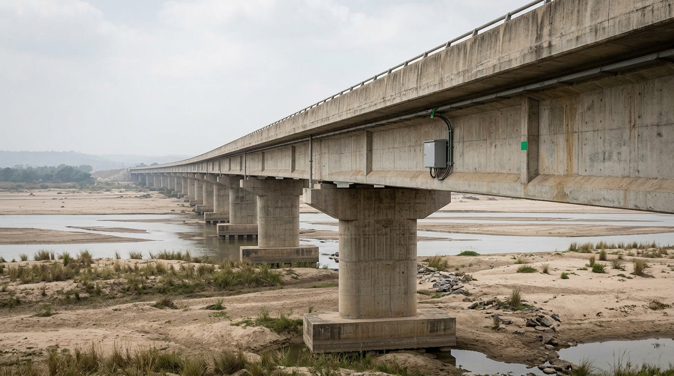
A bridge can remain visually serviceable while fatigue, bearing movement, scour, cable force variation, or foundation settlement develops between scheduled inspections. India’s Indian Bridge Management System (IBMS) provides a national framework for bridge inventory, condition assessment, inspection records, and maintenance prioritisation; instrumentation adds continuous evidence between inspections. This explains how does bridge health monitoring work for national highways in india, from defining the baseline to acting on an alert.
Bridge health monitoring is the planned measurement, interpretation, and reporting of structural and environmental responses so that bridge owners can identify deterioration, verify performance, and prioritise intervention.
For a National Highway asset, monitoring is not simply the installation of sensors or a dashboard. It is an engineered workflow connecting the bridge inspection regime, design information, traffic and weather conditions, data quality checks, threshold management, and decisions by the authority, supervision consultant, and maintenance contractor. The approach should be consistent with the bridge’s form, exposure, criticality, and known vulnerabilities, with reference to applicable IRC provisions including IRC SP-35, IRC SP-37, IRC:6, IRC:78, IRC:112, and IRC:114.
Key Takeaways
- Bridge health monitoring combines inspection, sensors, communications, analytics, engineering review, and documented action.
- The bridge monitoring process begins with a condition and risk assessment, not with selecting a sensor catalogue.
- Measured quantities may include strain, acceleration, tilt, displacement, temperature, bearing movement, cable response, and foundation-related movement.
- IBMS records and inspection findings provide asset context; continuous monitoring adds time-series evidence for critical locations.
- Alerts require validation against temperature, traffic, construction activity, sensor health, and structural engineering judgement.
How does bridge health monitoring work for national highways in India?
For a highway bridge, the process normally follows a controlled sequence: establish the asset record, identify failure modes, select measurable parameters, install and commission the monitoring system, collect time-stamped data, check data quality, interpret changes against a baseline, and issue actions through the owner’s management process. Each step has a different responsibility and output.
- Define the bridge and its risk context. Collect drawings, span arrangement, construction records, repair history, inspection reports, traffic classification, drainage details, bearing type, expansion joints, pier and abutment conditions, and exposure to flood, scour, seismic, or construction effects. The bridge’s location, route importance, detour implications, and inspection access affect monitoring priority.
- Identify credible deterioration or response mechanisms. Engineers translate observations into measurable risks. Examples include excessive deck strain, abnormal vibration, bearing restraint, pier tilt, differential settlement, cable force change, deck displacement, corrosion-related cracking, or hydraulic scour. A cable-stayed or extra-dosed bridge needs a different measurement strategy from a short reinforced-concrete slab bridge.
- Prepare the instrumentation plan. Select sensor type, range, accuracy, resolution, sampling rate, protection, mounting method, power arrangement, communication path, and calibration requirements. The plan should show sensor coordinates, channels, cable routes, junction boxes, reference points, and inspection access.
- Install without compromising the structure. Installation is coordinated with traffic management, waterproofing, utilities, bearings, expansion joints, and existing reinforcement. Mounting details must avoid introducing stress concentrations or creating corrosion paths. Photographs, as-built coordinates, serial numbers, calibration certificates, and installation checks become part of the asset record.
- Commission and establish a baseline. Engineers verify zero readings, channel continuity, time synchronisation, environmental compensation, noise level, and response to known events. A baseline may include normal temperature cycles, traffic passages, controlled loading where appropriate, and routine inspection observations. A baseline is not a single number; it is the expected response envelope under defined conditions.
- Transmit and store the measurements. A data acquisition system samples channels locally and transfers records through a suitable wired or wireless network. The system should retain raw data, processed values, timestamps, device status, power status, and communication logs. Real-time bridge data India deployments must account for intermittent connectivity, lightning, moisture, heat, dust, and remote access constraints.
- Validate and interpret the data. Automated rules flag missing values, drift, implausible jumps, flat-lined channels, time errors, and out-of-range readings. Engineers then separate environmental effects from structural change. For example, concrete and steel strain can vary with temperature; acceleration can change with traffic speed and vehicle mass; displacement can respond to thermal expansion or bearing movement.
- Convert evidence into action. A warning may require a site inspection, repeat measurement, traffic observation, drainage clearance, bearing examination, survey, or specialist analysis. A critical condition may require load restriction, lane control, temporary support, emergency inspection, or repair planning, subject to the authority’s approved procedure. The system is successful only when information reaches a responsible decision-maker with an auditable action trail.
Geolook’s structural health monitoring software for bridge data can support the data, alarm, visualisation, and reporting layer, while the engineering team remains responsible for interpreting the bridge response and approving interventions.
What does a bridge monitoring system measure?
A monitoring system measures parameters selected from the bridge’s structural form and risk register. The purpose is not to maximise channel count. It is to capture the response needed to test a defined engineering question: Is the deck strain within the expected range? Is a pier moving? Is a bearing translating? Has vibration behaviour changed? Is a cable-stayed bridge maintaining its expected force distribution?
Common measurements include strain in micro-strain, acceleration in m/s2 or mm/s2, displacement in mm, tilt in milliradians or degrees, temperature in °C, crack opening in mm, cable force in kN, corrosion potential in mV, pore-water pressure in kPa, and settlement in mm. Rainfall, water level, wind speed, and traffic counts may be added as explanatory variables.
Sensor selection should follow the mechanism. Vibrating-wire or electrical strain sensors may support long-term strain observation; accelerometers capture dynamic response; tiltmeters identify rotation; displacement transducers monitor movement at joints or bearings; GNSS or total-station observations can provide geometric control; and water-level or scour instruments can support hydraulic risk assessment. The relevant choice depends on range, resolution, environmental protection, calibration stability, installation access, and data frequency.
Decision makers should distinguish a measurement from a conclusion. A 2 mm displacement is not automatically unsafe, and a stable strain channel does not prove that every component is healthy. Meaning comes from location, direction, temperature, traffic, load history, inspection evidence, and comparison with design or analytical expectations. For more detail on instrumentation choices, see real time bridge monitoring sensors india.
How data moves from a sensor to an engineering decision
The bridge monitoring process has five information layers that should be visible in project documentation:
- Field layer: Sensors, protective enclosures, cables, wireless nodes, local data acquisition units, power supplies, and reference markers produce measurements at the bridge.
- Communication layer: Gateways transfer data to a server or cloud environment through the available network. Buffering is important where cellular coverage is intermittent, because a communication failure should not automatically be interpreted as a structural failure.
- Data layer: The platform stores raw and processed values with channel identity, engineering units, timestamps, quality flags, calibration information, and device diagnostics.
- Analytics layer: Algorithms and rules identify thresholds, trends, rate changes, correlations, frequency shifts, outliers, and missing data. Temperature compensation and event segmentation may be necessary before comparison.
- Decision layer: Alerts, plots, inspection notes, photographs, reports, and action registers are reviewed by authorised personnel. The output may be “observe,” “verify,” “inspect,” “analyse,” “restrict,” or “repair,” depending on evidence and the approved response matrix.
This separation helps prevent a common governance error: treating a red dashboard icon as a structural diagnosis. An alarm is a prompt for verification unless the monitoring plan defines the alarm as an immediately actionable condition. Every threshold should state its basis, unit, duration, affected component, confidence, and required response.
For bridges requiring a spatial operating view, RITES Ltd’s 3D Digital Twin and VR Visualization Platform for Bridge Health Monitoring System illustrates how geometry, inspection context, and measured behaviour can be presented together. A digital twin does not replace inspection or structural analysis; it improves the organisation of evidence around the asset.
IBMS, IRC provisions, and highway asset governance
IBMS is relevant because monitoring data becomes more useful when connected to an asset identity, location, component description, inspection history, condition rating, and maintenance record. A sensor channel without a clear bridge reference, component label, unit, and data owner is difficult to use during an incident or contract handover.
Monitoring specifications should be read alongside the bridge’s design and inspection requirements. IRC:6 addresses loads and load combinations; IRC:78 addresses foundations and substructures for highway bridges; IRC:112 addresses concrete bridge design; IRC:114 addresses guidelines for cement concrete mix design for road bridges; and IRC SP-35 and IRC SP-37 provide bridge inspection and maintenance-related guidance. The applicable edition, authority specification, concession agreement, and project-specific requirements should be confirmed before procurement.
For National Highway projects, the owner may be NHAI or another authorised road agency, with responsibilities distributed among the authority engineer, independent engineer, EPC contractor, O&M agency, specialist instrumentation firm, and data platform provider. The contract should define sensor ownership, calibration intervals, response time, cybersecurity, data retention, access rights, dashboard availability, replacement stock, and acceptance tests.
Monitoring should also be coordinated with routine and special inspections. A sensor trend can identify where to look; an inspection can establish the physical cause. The two records should be cross-referenced in the bridge register rather than maintained as disconnected reports.
Bridge monitoring methods for National Highway decision makers
The following comparison helps determine which monitoring mode fits a highway bridge. These modes are complementary rather than mutually exclusive.
| Monitoring mode | Typical evidence | Best use | Primary limitation | Decision output |
|---|---|---|---|---|
| Scheduled visual inspection | Cracks, spalling, corrosion, leakage, joint and bearing condition | Routine condition assessment and defect mapping | Conditions are observed at discrete times; concealed or rapidly changing behaviour may be missed | Maintenance item, rating update, or special inspection |
| Manual survey and level monitoring | Settlement, alignment, displacement, pier or abutment movement in mm | Geometric control and verification of suspected movement | Requires access, survey control, and repeat field visits | Trend confirmation or targeted investigation |
| Periodic instrument readings | Strain, tilt, crack opening, temperature, or vibration samples | Focused diagnosis where continuous power or connectivity is difficult | Events between readings may not be captured | Condition comparison at defined intervals |
| Continuous SHM | Time-series strain, acceleration, displacement, temperature, and device health | Critical bridges, unusual structures, construction influence, and event response | Needs engineering interpretation, maintenance, power, communications, and data governance | Alert, inspection trigger, trend report, or intervention recommendation |
| Load or controlled response test | Measured response under a defined test vehicle or loading condition | Commissioning, verification, or investigation | Represents a controlled event and may not reflect all operational conditions | Model correlation or acceptance evidence |
| Digital twin and visualisation | 3D geometry linked to inspection records and live or historical channels | Multi-party review, spatial understanding, and training | Visualisation quality depends on accurate asset and sensor metadata | Coordinated review and traceable communication |
How to specify and procure a bridge health monitoring system
A procurement document should begin with performance requirements rather than a brand or a list of devices. The employer should state the bridge inventory, monitoring objectives, critical components, expected environmental conditions, measurement ranges, accuracy, sampling requirements, data availability, alarm logic, reporting frequency, and required integration with inspection records.
Acceptance should include factory documentation where applicable, installation inspection, calibration traceability, channel naming, unit verification, time synchronisation, communication-loss testing, power-failure recovery, enclosure checks, baseline recording, and demonstration of alarm routing. The commissioning report should identify every sensor by bridge element, location, orientation, serial number, range, calibration status, and installation photograph.
Operational responsibility is equally important. A useful RACI matrix identifies who checks daily device status, who reviews weekly trends, who validates an alert, who visits the site, who approves traffic restrictions, and who closes the action. The contract should also define what happens when a sensor fails. A failed channel is a data-quality event; it should not be silently replaced by an interpolated value.
Geolook’s bridge monitoring work includes the supply of bridge health monitoring accessories for IIT-Mandi and a wireless DAQ application for Neeladari Buildtech. These references are relevant to procurement teams evaluating field accessories, wireless acquisition, installation coordination, and the separation between hardware supply and engineering interpretation.
When assessing bridge monitoring systems for Indian highway assets, ask for a sample data dictionary, alarm response matrix, commissioning checklist, maintenance schedule, and example event report. These documents reveal more about lifecycle readiness than a dashboard screenshot.
What happens after an alert?
An alert should start a defined verification sequence. First, the operator checks whether the channel is online, within calibration, correctly timestamped, and free from obvious noise or saturation. Second, the reviewer checks concurrent temperature, rainfall, traffic, construction, seismic, or hydraulic records. Third, the value is compared with neighbouring channels, historical behaviour, inspection records, and the baseline envelope.
If the anomaly remains credible, the authority may order a targeted inspection. The inspection should examine the physical component associated with the measurement: a bearing, expansion joint, deck zone, cable anchorage, pier, abutment, drainage path, or foundation environment. Depending on findings, the next step may include survey monitoring, non-destructive testing, structural analysis, load assessment, scour assessment, or repair design.
For long-span bridges, cable-stayed bridges, and extra-dosed bridges, specialist review is particularly important because system behaviour is coupled. Sandeep Gupta, IRSE and former Chief Administrative Officer of Indian Railways, contributes domain expertise in cable-stayed, extra-dosed, and long-span bridge engineering through Geolook’s advisory practice. Such expertise helps connect measured response with structural form and operational context.
The action record should preserve the original alert, quality checks, engineering interpretation, inspection evidence, decision authority, mitigation, and closure criteria. This creates a defensible history for future inspections, maintenance budgeting, concession handover, and incident review.
Frequently Asked Questions
Q: What is bridge health monitoring for National Highways?
A: Bridge health monitoring for National Highways is a structured system for observing bridge condition and response through inspections, sensors, data acquisition, analysis, and engineering action. It can track strain, acceleration, displacement, tilt, temperature, cable response, bearing movement, and related environmental variables, while connecting findings to the asset record and maintenance workflow.
Q: How does bridge health monitoring work for national highways in india?
A: How does bridge health monitoring work for national highways in india is answered by its sequence: define risks, select parameters, install and commission instruments, establish a baseline, transmit time-stamped data, validate readings, interpret trends, and act on verified anomalies. The process supplements IBMS records and inspections; it does not replace structural engineering judgement or statutory authority procedures.
Q: What sensors are commonly used on highway bridges?
A: Sensors commonly used on highway bridges include strain gauges, accelerometers, displacement transducers, tiltmeters, temperature sensors, crack-width gauges, cable-force instruments, corrosion sensors, water-level devices, and survey or GNSS equipment. The appropriate combination depends on the bridge type, suspected failure mechanism, measurement range, environmental exposure, access, power, communications, and required response time.
Q: Does real-time bridge data India require continuous internet connectivity?
A: Real-time bridge data India does not always require uninterrupted internet connectivity because a suitable acquisition system can buffer readings locally and transmit them when communication is restored. The specification should define data-loss limits, local storage duration, time synchronisation, communication alarms, power backup, and how operators distinguish a network outage from a structural event.
Q: What should an authority do when a bridge monitoring alarm appears?
A: An authority should first verify the alarm as a data-quality and engineering event before ordering intervention. The review should check sensor status, calibration, timestamp, temperature, traffic, weather, neighbouring channels, and recent site activity. If the anomaly persists, the authority should initiate the approved inspection or restriction procedure and document the decision, evidence, responsible officer, and closure criteria.
See live bridge demo
See how a bridge monitoring workflow can bring sensor channels, asset geometry, alarms, inspection context, and reports into one review environment. A practical demonstration can be structured around a National Highway bridge’s risk register, baseline, alert matrix, and handover requirements.
Explore Geolook’s transport infrastructure intelligence solutions for Indian bridges or request a project discussion through the Geolook bridge monitoring team.
Project inquiry
Talk to a Geolook™ specialist
Share your monitoring requirement and our team will help identify the right next step.
By submitting, you agree that Geolook™ may contact you about this inquiry. Your details are not added to a marketing list.