Real-Time Sensor Monitoring During Underground Tunnel Excavation
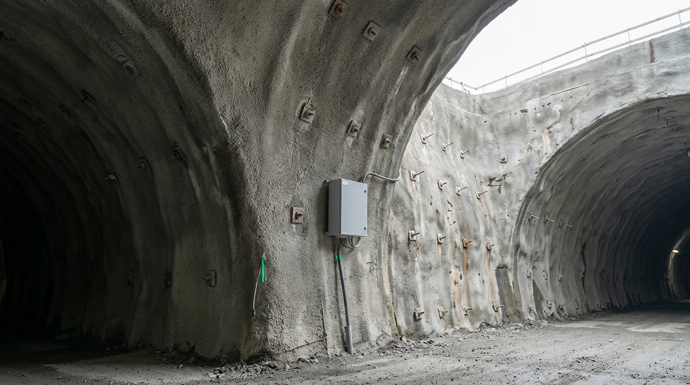
In November 2022, a section of the Banihal-Qazigund road tunnel on NH-44 in Jammu & Kashmir experienced a sudden ingress of water and debris, disrupting traffic on one of India's most strategically critical mountain corridors. The incident underscored a recurring reality in Indian tunnel construction: ground behaviour during excavation is rarely as predicted by pre-construction geological surveys, and the margin between a manageable deformation event and a structural emergency is measured in millimetres and hours. Real time sensor monitoring during underground tunnel excavation is not an instrumentation upgrade — it is the primary mechanism by which tunnel engineers detect, interpret, and respond to ground-structure interaction before it becomes irreversible.
This post covers the sensor types, deployment phases, convergence thresholds, and data interpretation protocols that define a technically defensible tunnel monitoring programme, with reference to ISRM guidelines, Indian practice, and field experience from active projects.
Key Takeaways
- Real time sensor monitoring during underground tunnel excavation provides continuous ground-structure interaction data that manual survey rounds cannot replicate, particularly during the critical 24–72 hours after each excavation advance.
- ISRM recommends convergence monitoring at every 5–10 m of tunnel advance in variable ground; Indian NATM practice on NH projects typically sets alert thresholds at 50% of the maximum allowable deformation.
- A phase-specific sensor deployment strategy — face, ring-closure, and far-field — reduces instrumentation cost while maintaining coverage at the highest-risk locations.
- Vibrating-wire sensors, MEMS accelerometers, and fibre-optic strain gauges each serve distinct measurement roles; no single transducer type covers all required parameters.
- Data from the Ramban-Banihal NH-44 tunnel corridor, monitored in association with DRAIPL and reviewed with the NHAI Regional Office, demonstrates that multi-sensor real-time networks enable proactive support decisions rather than reactive repair.
What Real-Time Sensor Monitoring During Underground Tunnel Excavation Means
Real time sensor monitoring during underground tunnel excavation is the continuous, automated acquisition and transmission of geomechanical and structural parameters — including displacement, strain, pore pressure, and vibration — from sensors installed within and around an advancing tunnel, enabling engineers to compare measured values against pre-defined threshold criteria without waiting for manual survey cycles.
The distinction from periodic manual monitoring is not merely speed. Manual tape-extensometer or total-station surveys, conducted once or twice per shift, produce a time-series with gaps of 8–12 hours. Ground deformation in weak rock or saturated soil can accelerate from 0.5 mm/day to 5 mm/day within a single shift following an excavation blast or a rainfall event. A real-time network with scan rates of 1–10 minutes captures that acceleration curve; a manual survey misses it entirely.
For tunnel excavation monitoring systems to function as decision-support tools, the data pipeline must close within minutes: sensor → data acquisition unit (DAQ) → edge processing → cloud or on-site server → alert dispatch. Latency beyond 15 minutes in a fast-moving NATM face negates much of the safety benefit.
Ground Behaviour and Why Sensors Must Track It Continuously
Underground excavation disturbs the in-situ stress field. As the tunnel face advances, a zone of stress redistribution — the plastic zone — develops around the opening. In competent rock, this zone stabilises within one to two tunnel diameters behind the face. In weak, jointed, or water-bearing ground, the plastic zone can extend four to six diameters and continue to evolve for days or weeks after excavation.
The New Austrian Tunnelling Method (NATM), which governs most Indian highway and railway tunnel construction, treats the surrounding ground as a load-bearing structural element. Primary support — shotcrete lining, rock bolts, and steel ribs — is designed to mobilise ground arching rather than resist the full overburden. This philosophy is inherently observational: support adequacy is verified by measuring actual deformation, not by calculation alone. IS 15026:2002 (Tunnelling in Rock — Code of Practice) and the ISRM Suggested Methods for Monitoring Rock Movements both require that convergence and crown settlement data be collected and reviewed against design thresholds throughout construction.
ISRM defines three warning levels for tunnel convergence monitoring: Green (deformation rate below 1 mm/day, no action required), Amber (1–5 mm/day, increased monitoring frequency and engineering review), and Red (above 5 mm/day or total convergence exceeding the design limit, immediate work stoppage and support review). Indian NHAI project specifications on NH-44 and similar mountain corridors typically adopt these thresholds with project-specific adjustments based on rock mass rating (RMR) and tunnel diameter.
Sensors that feed IoT-enabled tunnel monitoring networks allow the site team to track deformation rate — not just cumulative deformation — in real time, which is the parameter that ISRM and IS 15026 identify as the primary indicator of impending instability.
Phase-Specific Sensor Deployment: From Face to Far-Field
Tunnel excavation monitoring is most effective when instrumentation is matched to the geomechanical processes dominant at each construction phase. The table below maps sensor types to excavation phases, measured parameters, and typical installation locations.
| Excavation Phase | Sensor Type | Measured Parameter | Typical Location | Output Unit |
|---|---|---|---|---|
| Face advance (0–1D behind face) | Vibrating-wire (VW) shotcrete stress cell | Tangential stress in primary lining | Embedded in first shotcrete layer, crown and shoulders | kPa |
| Face advance (0–1D behind face) | Tape extensometer / automated total station | Horizontal convergence, crown settlement | Monitoring cross-sections at 5–10 m spacing | mm |
| Ring closure (1–3D behind face) | VW rock bolt load cell | Axial load in rock bolt | Selected bolts at crown and haunches | kN |
| Ring closure (1–3D behind face) | MEMS tiltmeter | Rotation of lining segments | Invert and shoulder sections | degrees / mrad |
| Ring closure (1–3D behind face) | VW piezometer | Pore water pressure in surrounding ground | Drilled boreholes, 2–5 m from tunnel wall | kPa |
| Far-field (>3D behind face) | Multi-point borehole extensometer (MPBX) | Rock mass displacement at multiple depths | Boreholes drilled from tunnel wall or surface | mm |
| Far-field (>3D behind face) | Vibration monitor (geophone) | Peak particle velocity from blasting | Lining surface and adjacent structures | mm/s |
| Secondary lining and long-term | Fibre-optic distributed strain sensor (DSS) | Distributed strain along lining | Embedded in secondary concrete lining | micro-strain (με) |
| Secondary lining and long-term | Crack meter (VW or potentiometric) | Joint opening / crack width | Construction joints, identified crack locations | mm |
The VW shotcrete stress cell deserves particular attention at the face-advance phase. Shotcrete in a NATM tunnel is not passive formwork — it is a structural element carrying tangential compressive stress that can reach 4–8 MPa in squeezing ground. A stress cell embedded at the time of shotcrete application provides a direct measure of lining load, allowing the engineer to verify that the primary support is neither overloaded nor under-mobilised. Without this measurement, lining adequacy is inferred from deformation alone, which is an indirect and lagging indicator.
Convergence Monitoring: Thresholds, Instruments, and Interpretation
Convergence monitoring is the measurement of the change in distance between two fixed points on opposite walls of a tunnel cross-section, used to quantify the inward displacement of the tunnel boundary over time. It is the most widely specified parameter in tunnel construction contracts in India and internationally.
ISRM Suggested Method for Monitoring Rock Displacements Using Tape Extensometers (Brown, 1981, updated 2007) specifies measurement accuracy of ±0.1 mm for tape extensometers and recommends that readings be taken at least once per shift during active excavation within two tunnel diameters of the monitoring section. Automated total stations and robotic prism-based systems can achieve ±0.3–0.5 mm accuracy at ranges up to 150 m and can scan a full cross-section of monitoring prisms in under two minutes, making them the preferred instrument for real time sensor monitoring during underground tunnel excavation in long tunnels where manual access is restricted.
On the Ramban-Banihal NH-44 tunnel corridor — where Geolook deployed real-time SHM across five tunnels in association with DRAIPL, with data reviewed at NHAI Regional Office level — convergence cross-sections were established at 10 m intervals through zones of poor rock mass (RMR < 40). Alert thresholds were set at 50% of the design maximum convergence for the Amber level and 80% for the Red level, consistent with NHAI's standard instrumentation and monitoring specifications for mountain tunnels.
Interpretation of convergence data requires more than threshold comparison. The Peck (1969) settlement trough model and the Vlachopoulos-Diederichs (2009) longitudinal displacement profile are both used to distinguish face-effect deformation (which stabilises as the face advances away) from time-dependent creep or swelling (which continues after face passage). A real-time system that logs timestamps against chainage allows the engineer to separate these two mechanisms and adjust support accordingly. Explore how structural health monitoring for bridges dams and tunnels india applies these principles across infrastructure asset classes.
Data Acquisition, Telemetry, and Alert Architecture
A tunnel monitoring network is only as useful as its data pipeline. In underground environments, wired Modbus or RS-485 networks connecting VW readout units to a surface DAQ remain the most reliable topology for permanent installations, given the attenuation of radio signals through rock and concrete. For temporary face-advance instrumentation, short-range wireless protocols (LoRa, Zigbee) are used where cable routing is impractical, with a gateway unit positioned at the tunnel portal or an intermediate adit.
DAQ scan rates for tunnel monitoring are typically set at 1–15 minutes for deformation sensors during active excavation, stepping down to 1–4 hours after ring closure and 6–24 hours during the long-term monitoring phase. Vibration monitors triggered by blast events require continuous sampling at 1–4 kHz to capture peak particle velocity (PPV) accurately; IS 2386 and DGMS (Directorate General of Mines Safety) guidelines specify PPV limits for adjacent structures, typically 5–10 mm/s for masonry and 25–50 mm/s for reinforced concrete.
Alert architecture should implement three-tier thresholds: Green (normal operation, automated logging), Amber (automated SMS/email to site engineer and geotechnical consultant, increased scan rate), Red (automated alert to project manager and NHAI/client representative, work stoppage protocol initiated). The MIT-WPU Tunnel Health Monitoring and Digital Twin Excellence Centre in Pune — inaugurated by Minister Sh. Nitin Gadkari — is developing standardised alert and digital twin protocols for Indian tunnel projects, providing a research and training framework that supports this kind of tiered response architecture.
For projects requiring integrated sensor management across multiple tunnel structures, underground infrastructure monitoring solutions provide the system architecture to connect face-advance instrumentation, permanent lining sensors, and surface settlement arrays into a single data environment.
Surface and Third-Party Structure Monitoring During Tunnel Excavation
Tunnel excavation monitoring does not end at the tunnel boundary. Volume loss during excavation propagates to the surface as a settlement trough, the geometry of which is described by the Gaussian distribution model (Peck, 1969). For urban tunnels — metro rail, road underpasses, utility tunnels — the settlement trough may intersect building foundations, buried utilities, or adjacent tunnel structures.
IS 1892:1979 (Code of Practice for Site Investigations for Foundations) and the CPWD guidelines for urban tunnelling specify that surface settlement monitoring must be established before excavation commences and maintained until ground movements have stabilised. Typical instrumentation includes surface settlement points (precise levelling or GNSS), building tiltmeters, crack meters on adjacent structures, and inclinometers in boreholes flanking the tunnel alignment.
For metro construction in Indian cities, where tunnel drives pass within 5–15 m of existing metro lines, buildings, and utilities, the monitoring density and alert thresholds are significantly more stringent. The metro construction monitoring framework addresses these requirements in detail, including the specific sensor types and threshold criteria used on urban tunnel projects.
Peak particle velocity from tunnel blasting is a critical parameter for third-party structure protection. ISRM and DGMS guidelines require PPV monitoring at the nearest sensitive structure for every blast round. Geophone-based vibration monitors with onboard data logging and GSM telemetry allow blast records to be transmitted to the client and regulatory authority within minutes of each event, supporting compliance documentation under the Explosives Act and DGMS regulations.
Sensor Selection Criteria for Indian Tunnel Conditions
Indian tunnel projects span a wide range of ground conditions: the Himalayan and sub-Himalayan geology of J&K, Uttarakhand, and Himachal Pradesh presents weak, highly jointed, and often water-bearing rock; the Deccan Basalt of Maharashtra and Karnataka is generally competent but subject to localised fault zones; alluvial and soft ground conditions dominate urban metro tunnels in Delhi, Mumbai, Bangalore, and Chennai.
Sensor selection must account for these conditions. Vibrating-wire sensors are preferred for long-term installations in wet environments because the frequency-based output is immune to cable resistance changes caused by moisture ingress — a significant advantage over resistance-based (Wheatstone bridge) sensors in Himalayan tunnels where groundwater inflows are common. VW sensors also have a proven track record of stability over multi-year monitoring periods, which is relevant for tunnels that require post-construction monitoring under NHAI's asset management requirements.
MEMS-based sensors offer lower cost per channel and are suitable for dense arrays in the face-advance zone where instruments may be lost to blast damage and require replacement. Fibre-optic distributed sensing (BOTDA or OFDR) provides strain measurement along the full length of a sensor cable embedded in the lining, which is particularly valuable for detecting localised cracking in secondary concrete linings that point sensors would miss.
A comprehensive overview of sensor types, specifications, and selection criteria for tunnel applications is available through the geotechnical and structural sensor product range.
Digital Integration and the Observational Method
The Observational Method, codified in Eurocode 7 (EN 1997-1) and referenced in Indian geotechnical practice, requires that monitoring data be used to verify design assumptions and trigger pre-defined contingency actions when measurements deviate from predicted behaviour. Real time sensor monitoring during underground tunnel excavation is the technical implementation of this method: it closes the feedback loop between design prediction and field measurement.
Digital integration — connecting sensor data to a geotechnical model or digital twin — extends this capability. When convergence rates, shotcrete stress, and pore pressure data are visualised against the tunnel chainage and geological profile in a single dashboard, the geotechnical engineer can identify spatial patterns that are invisible in tabular data: a zone of accelerating convergence correlating with a mapped fault, or a pore pressure spike preceding a face instability event.
The MIT-WPU Tunnel Health Monitoring and Digital Twin Excellence Centre is building the research and training infrastructure to support this level of integration for Indian tunnel projects, including AI-assisted anomaly detection and VR-based training for instrumentation engineers. For engineers working on urban metro structures, the detailed sensor and system frameworks described in what sensors and systems are used in tunnel health monitoring for urban metro projects provide a directly applicable reference.
The combination of phase-specific instrumentation, real-time data acquisition, tiered alert thresholds, and digital integration represents the current standard of practice for tunnel excavation monitoring in India. It is not a technology aspiration — it is the minimum required to implement the Observational Method as intended by IS 15026 and ISRM guidelines.
Frequently Asked Questions
Q: What is convergence monitoring in tunnel excavation?
A: Convergence monitoring is the systematic measurement of inward displacement of a tunnel's boundary walls over time, used to verify that ground deformation remains within design limits. ISRM recommends measurements at every 5–10 m of advance in variable ground, with alert thresholds typically set at 50% and 80% of the maximum allowable convergence for Amber and Red warning levels respectively.
Q: Which sensors are most critical during the face-advance phase of NATM tunnelling?
A: During the face-advance phase, VW shotcrete stress cells embedded in the primary lining and tape extensometers or automated total-station prisms at convergence cross-sections are the most critical sensors. Shotcrete stress cells provide direct measurement of lining load in kPa, while convergence instruments track boundary displacement in mm — together they verify primary support adequacy as the face advances.
Q: What convergence rate triggers a work stoppage in Indian tunnel projects?
A: A convergence rate exceeding 5 mm/day is the ISRM Red-level threshold that typically triggers work stoppage and immediate engineering review. Indian NHAI mountain tunnel specifications generally adopt this threshold, adjusted for tunnel diameter and rock mass rating. Total convergence exceeding 80% of the design maximum is an independent trigger regardless of rate.
Q: How does real time sensor monitoring during underground tunnel excavation differ from manual survey monitoring?
A: Real time sensor monitoring during underground tunnel excavation provides continuous automated data at scan intervals of 1–15 minutes, capturing deformation acceleration events that occur within a single shift. Manual survey rounds conducted once or twice per shift produce 8–12 hour data gaps, during which ground behaviour can change from stable to critical without detection, particularly in weak or water-bearing ground.
Q: What Indian standards govern tunnel instrumentation and monitoring?
A: IS 15026:2002 (Tunnelling in Rock — Code of Practice) is the primary Indian standard governing tunnel construction monitoring requirements. ISRM Suggested Methods provide internationally recognised protocols for convergence measurement, rock bolt load testing, and borehole extensometry. DGMS guidelines govern blast vibration monitoring under the Explosives Act, specifying PPV limits for adjacent structures.
View tunnel sensors
Geolook supplies and deploys the full instrumentation stack for real time sensor monitoring during underground tunnel excavation — from VW shotcrete stress cells and MPBX extensometers at the face to fibre-optic distributed strain sensors in the secondary lining. Our systems are field-proven on the Ramban-Banihal NH-44 tunnel corridor and are aligned with ISRM, IS 15026, and NHAI monitoring specifications.
To review sensor specifications, system architecture options, or to discuss instrumentation requirements for your tunnel project, contact the Geolook engineering team or explore the full product range.
View the complete tunnel excavation monitoring system range or contact Geolook to discuss your project instrumentation requirements.
Project inquiry
Talk to a Geolook™ specialist
Share your monitoring requirement and our team will help identify the right next step.
By submitting, you agree that Geolook™ may contact you about this inquiry. Your details are not added to a marketing list.