Groundwater Monitoring: Piezometers, Standpipes & Real-Time Tracking
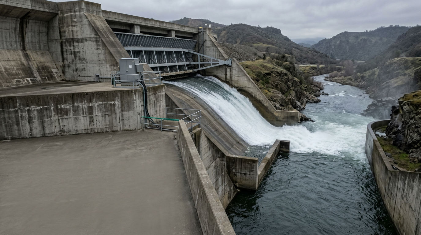
In August 2018, the Ockhi cyclone-driven rainfall caused the Mullaperiyar reservoir in Kerala to approach its full reservoir level of 142 feet, triggering emergency spillway operations and evacuations affecting over a million people downstream — a stark reminder that unmonitored groundwater and seepage conditions inside dam bodies can escalate from a data gap into a public safety crisis within hours. For dam engineers and hydrogeologists operating under India's Dam Safety Act 2021, systematic groundwater monitoring is no longer discretionary; it is a statutory obligation for all large dams under the National Dam Safety Authority (NDSA) framework.
This guide covers the instrumentation systems, installation protocols, and regulatory context that define a technically defensible groundwater monitoring programme — from open standpipe piezometers to vibrating wire sensors feeding real-time dashboards. Whether you are designing a new observation well network under CGWB guidelines or retrofitting an ageing embankment dam with automated water level sensors, the engineering decisions here directly affect the reliability of your seepage and pore pressure data.
Key Takeaways
- Groundwater monitoring in dams is mandated under the Dam Safety Act 2021 and must align with CWC guidelines for instrumentation and observation well design.
- Vibrating wire piezometers offer resolution to ±0.025% full scale and response times under one second, making them the preferred sensor for real-time pore pressure tracking in embankment dams.
- CGWB well construction standards specify casing diameter, screen slot size, and gravel pack gradation — non-compliance directly compromises water level sensor accuracy.
- Open standpipe systems remain valid for long-term baseline monitoring where response lag is acceptable, but they cannot support automated alarming at sub-hourly intervals.
- A complete groundwater monitoring system integrates sensor, datalogger, telemetry, and SCADA or cloud dashboard into a single traceable data chain.
What Is Groundwater Monitoring?
Groundwater monitoring is the systematic measurement, recording, and analysis of subsurface water levels, pore water pressures, and seepage flows at defined spatial and temporal intervals to assess aquifer behaviour, structural safety, or environmental compliance. In the context of dam safety, the primary objective is to detect anomalous pore pressure build-up within embankment fills, foundations, or abutments before it reaches a threshold that could initiate piping, slope instability, or hydraulic fracture.
Under IS 7894 (Code of Practice for Stability Analysis of Earth Dams), piezometric data is a direct input to effective stress calculations. A rise in piezometric head of even 0.5 m in a critical zone can shift the factor of safety for an upstream slope by a measurable margin, depending on the shear strength parameters of the fill material. This is why the CWC's Guidelines for Safety Inspection of Dams (2019 revision) require piezometer readings at a minimum frequency of once per week during monsoon and once per fortnight during non-monsoon periods for Class I dams.
For hydrogeologists working on aquifer characterisation under CGWB's National Aquifer Mapping and Management Programme (NAQUIM), groundwater monitoring extends to water table fluctuation, seasonal recharge estimation, and long-term trend analysis across observation well networks that may span hundreds of square kilometres.
Piezometer Types and Their Engineering Basis
The choice of piezometer type governs the temporal resolution, installation depth, response lag, and maintenance burden of your groundwater monitoring programme. Three instrument families dominate dam and geotechnical applications in India.
Open Standpipe (Casagrande) Piezometers consist of a perforated tip set in a sand filter zone, connected to a surface standpipe. Water level is measured manually using a dipmeter or electronically using a float-type or pressure transducer water level sensor. Response time depends on the hydraulic conductivity of the surrounding soil; in low-permeability clays (k < 10⁻⁸ m/s), equilibration can take days to weeks, making them unsuitable for tracking rapid pore pressure changes during reservoir filling or flood events.
Vibrating Wire Piezometers (VWP) measure pore water pressure by detecting the resonant frequency of a tensioned steel wire connected to a diaphragm. A change in pressure deflects the diaphragm, altering wire tension and therefore frequency. The relationship between frequency squared and pressure is linear and highly stable over temperature ranges of −20°C to +80°C. Resolution is typically ±0.025% full scale, and full-scale ranges from 35 kPa to 3,500 kPa are available. VWPs can be read remotely at intervals of seconds to minutes, enabling real-time alarming. Explore the vibrating wire piezometer sensor specifications for full-scale range and accuracy data relevant to your project.
Pneumatic Piezometers use twin-tube pneumatic circuits to measure pressure at the tip. They are robust in aggressive chemical environments but require a pneumatic readout unit and are not easily automated for continuous telemetry. Their use in new installations has declined significantly as VWP costs have fallen.
For a deeper understanding of how VWP technology applies to dam embankment safety, see the technical discussion on vibrating wire piezometer working principle.
Observation Well Design Under CGWB Guidelines
The Central Ground Water Board's Manual on Artificial Recharge of Ground Water and its companion well construction standards specify minimum design criteria for observation wells intended for water level monitoring. Key parameters include:
- Casing diameter: Minimum 100 mm internal diameter for wells accommodating a water level sensor or dipmeter; 150 mm where pump testing is also planned.
- Screen slot size: Selected to retain 85–90% of the natural formation material, typically 0.5–1.5 mm for medium sands common in Indo-Gangetic alluvial aquifers.
- Gravel pack gradation: Pack material D50 should be 4–6 times the D50 of the formation sand to prevent fine migration while maintaining hydraulic connectivity.
- Seal depth: A bentonite seal of minimum 3 m thickness above the gravel pack prevents surface water infiltration, which would corrupt piezometric readings.
- Well development: Surging and pumping to achieve turbidity below 10 NTU before baseline readings are established.
Non-compliance with these specifications is the most common cause of erratic water level sensor readings in the field. A poorly developed well introduces air entrainment and fine particle migration that create false pressure transients, particularly in VWP installations where the diaphragm is sensitive to particulate impingement.
IS 2720 (Part 36) provides the laboratory test methods for soil classification that inform screen slot selection, while IS 1892 covers subsurface investigation procedures relevant to siting observation wells in dam foundations.
Piezometer Installation in Embankment Dams
Installation methodology differs substantially between drilled-in piezometers in existing dams and instruments placed during construction. Both scenarios require careful attention to the hydraulic seal between measurement zones.
Construction-stage installation allows VWPs to be placed at precise elevations within the fill as compaction proceeds. The instrument is embedded in a sand pocket (typically 300 mm diameter, 600 mm tall) surrounded by fine sand, with a bentonite pellet seal above to isolate the measurement zone from adjacent fill. Cables are routed horizontally to the downstream face in conduits, with anti-seepage collars at every 3 m to prevent preferential seepage along the cable trench.
Drilled-in installation in existing embankments uses rotary or percussion drilling to reach the target depth. The borehole is completed with a sand filter zone around the piezometer tip, a bentonite seal above, and a grout column to surface. Multiple piezometers can be installed in a single borehole using the multiple-point borehole extensometer approach, provided each zone is hydraulically isolated — a requirement explicitly stated in CWC dam instrumentation guidelines.
For dam safety engineers seeking a broader view of instrumentation strategy, the guide on dam safety monitoring covers the full instrument suite from inclinometers to settlement gauges alongside piezometric systems.
Post-installation, each VWP should be subjected to a pneumatic pressure test to verify diaphragm integrity before the borehole is sealed. Baseline readings over a minimum 72-hour period, with the reservoir at a known level, establish the reference datum against which all subsequent readings are compared.
Comparison of Groundwater Monitoring System Types
The table below compares the principal piezometer and water level sensor systems used in dam safety and hydrogeological applications across key engineering parameters.
| Parameter | Open Standpipe Piezometer | Vibrating Wire Piezometer | Pneumatic Piezometer | Pressure Transducer (Submersible) |
|---|---|---|---|---|
| Measurement principle | Hydraulic head (manual dipmeter or float sensor) | Resonant frequency of tensioned wire | Pneumatic back-pressure balance | Strain-gauge or capacitive diaphragm |
| Typical full-scale range | Depth of well (no pressure limit) | 35 kPa – 3,500 kPa | Up to 700 kPa | 0–100 m H₂O (typical) |
| Resolution | ±5–10 mm (manual); ±1 mm (electronic) | ±0.025% FS (~0.1 kPa at 350 kPa FS) | ±0.1% FS | ±0.05% FS |
| Response time in low-k soils | Days to weeks (k < 10⁻⁸ m/s) | Seconds (sealed diaphragm, no flow required) | Minutes (pneumatic equilibration) | Seconds (if in open water column) |
| Automated / real-time capable | Only with add-on water level sensor | Yes — direct datalogger connection | No — manual readout unit required | Yes — 4–20 mA or SDI-12 output |
| Long-term stability | High (simple mechanical system) | High (frequency-based, drift <0.1% FS/year) | Moderate (tube permeation over time) | Moderate (zero drift possible) |
| Suitability for Dam Safety Act 2021 real-time reporting | Limited (manual reading frequency) | Fully suitable | Not suitable | Suitable in open standpipes |
Real-Time Groundwater Monitoring: Telemetry and Data Management
A real-time groundwater monitoring system is only as reliable as its weakest data link. The sensor chain from VWP diaphragm to engineer dashboard involves four components: the sensor itself, a datalogger with signal conditioning, a telemetry link, and a data management platform.
Dataloggers for dam applications must support multiplexed VWP reading (typically via frequency counter or period-averaging circuits), on-board storage for at least 90 days of data at 15-minute intervals, and battery-backed operation during grid outages. Reading resolution should be better than 0.1 Hz to preserve the ±0.025% FS accuracy of the VWP.
Telemetry options in Indian dam environments include GSM/4G cellular (suitable where network coverage exists), VSAT (for remote Himalayan or northeastern dam sites), and LoRaWAN mesh networks for instrument clusters within a 5–10 km radius. The NDSA's draft guidelines for automated dam safety monitoring recommend redundant communication paths for Class I dams.
Alarm thresholds are set at two levels: a warning level (typically 80% of the design piezometric head) and an action level (90–95%), above which the dam safety officer must be notified within 30 minutes. These thresholds are derived from the stability analysis performed under IS 7894 and must be reviewed after every major flood event or reservoir operation cycle.
Hydrogeologists working on energy sector reservoirs — hydropower dams and pump-storage projects — face additional complexity from rapid reservoir level fluctuations. The application of real-time piezometric data in these contexts is discussed in the energy sector infrastructure monitoring solutions section of the Geolook platform.
For engineers who need to understand how pore pressure data integrates into dam safety decision-making, the detailed technical resource on real time pore water pressure monitoring in dams provides the analytical framework for threshold setting and trend interpretation.
Regulatory and Standards Framework for Groundwater Monitoring in India
India's regulatory landscape for groundwater monitoring spans three overlapping frameworks depending on the application context.
Dam Safety Act 2021 mandates that all large dams (height ≥ 15 m, or 10–15 m with specific storage or flood discharge criteria) maintain a comprehensive instrumentation and monitoring programme. The Act establishes the National Dam Safety Authority and State Dam Safety Organisations (SDSOs) as the enforcement bodies. Failure to maintain functional piezometric monitoring is a compliance deficiency that can trigger SDSO intervention.
CWC Guidelines for Safety Inspection of Dams specify minimum instrument types, reading frequencies, and data reporting formats. For embankment dams, piezometers are classified as mandatory instruments alongside settlement gauges and seepage measurement weirs. The guidelines reference IS 7894 for stability analysis and IS 11130 for seepage measurement.
CGWB Regulatory Framework under the Model Groundwater (Sustainable Management) Bill 2017 requires groundwater users above a defined extraction threshold to install and maintain observation wells conforming to CGWB well construction standards. Water level data must be submitted to the State Ground Water Authority at quarterly intervals.
For geotechnical engineers, IS 1892 (Site Investigation for Foundations) and IS 2720 (Methods of Test for Soils) provide the test protocols that underpin aquifer characterisation and well design. IS 14458 (Retaining Walls for Hill Area) is relevant where groundwater monitoring supports slope stability assessment adjacent to dam abutments.
Frequently Asked Questions
Q: What is the difference between a piezometer and a standpipe observation well?
A: A piezometer measures pore water pressure at a specific isolated depth interval, while a standpipe observation well measures the composite water level across an open screened interval. Piezometers — particularly vibrating wire types — provide zone-specific pressure data in kPa with sub-second response, whereas standpipes reflect an averaged hydraulic head and respond slowly in low-permeability soils.
Q: How often should piezometer readings be taken in a dam under the CWC guidelines?
A: CWC guidelines for Class I dams require piezometer readings at minimum weekly frequency during monsoon season and fortnightly during non-monsoon periods. For dams with automated real-time systems, continuous logging at 15-minute intervals is recommended by NDSA draft guidelines, with alarm thresholds set at 80% and 90–95% of the design piezometric head derived from IS 7894 stability analysis.
Q: What full-scale pressure range should I specify for a vibrating wire piezometer in an embankment dam?
A: Select a VWP full-scale range that is 1.5 to 2 times the maximum anticipated pore pressure at the installation depth. For a 30 m high embankment with a phreatic surface near the crest, the maximum pore pressure at the base is approximately 294 kPa (30 m × 9.81 kN/m³), so a 350 kPa or 700 kPa full-scale instrument is appropriate, preserving resolution while avoiding over-ranging.
Q: Can a water level sensor be used in place of a vibrating wire piezometer for dam safety monitoring?
A: A submersible pressure transducer water level sensor installed in an open standpipe can provide automated readings but is limited by the standpipe's response lag in low-permeability soils. For real-time pore pressure monitoring in embankment fills where hydraulic conductivity is below 10⁻⁷ m/s, a sealed vibrating wire piezometer is the technically correct choice because it requires no water flow to equilibrate.
Q: What CGWB standards govern observation well construction for groundwater monitoring?
A: CGWB's Manual on Artificial Recharge of Ground Water and associated well construction guidelines specify minimum 100 mm internal casing diameter, screen slot sizing to retain 85–90% of formation material, a gravel pack with D50 four to six times the formation D50, and a minimum 3 m bentonite seal above the filter zone. Wells must be developed to below 10 NTU turbidity before baseline water level readings are recorded.
View groundwater solutions
Geolook's instrumentation team supports dam engineers and hydrogeologists from instrument selection through to real-time dashboard commissioning. Whether your project requires embedded VWPs during embankment construction, drilled-in piezometers for an existing dam safety upgrade, or a CGWB-compliant observation well network for aquifer monitoring, the technical configuration must be matched to your soil profile, monitoring frequency requirement, and telemetry constraints.
Review the full range of groundwater monitoring instruments and systems available through Geolook, including dataloggers, telemetry units, and cloud-based data management platforms configured for Indian dam safety and hydrogeological applications.
To discuss your specific project requirements — including instrument selection, installation methodology, and compliance with Dam Safety Act 2021 or CGWB well construction standards — contact the Geolook engineering team for a technical consultation.
Project inquiry
Talk to a Geolook™ specialist
Share your monitoring requirement and our team will help identify the right next step.
By submitting, you agree that Geolook™ may contact you about this inquiry. Your details are not added to a marketing list.