Geotechnical Sensor Comparison for Indian Projects
On a high-rise or tunnel project, a sensor rarely fails because its datasheet is inadequate; it fails because its measurement principle does not match the soil, structure, cable route, temperature range, or inspection plan. In India, where settlement, excavation movement, seismic demand and construction staging often overlap, procurement teams need more than a catalogue comparison. This geotechnical sensor comparison provides a vendor-neutral engineering framework for selecting vibrating-wire (VW), micro-electromechanical system (MEMS) and fibre-optic instruments.
A geotechnical sensor comparison is a structured evaluation of measurement principle, measurand, accuracy, environmental suitability, installation, data acquisition and lifecycle risk before an instrument is specified. The framework is relevant to instrumentation plans prepared with reference to IS 1892 for subsurface investigations, IS 2720 test methods, IS 1893 for seismic considerations, and project-specific requirements from NHAI, RVNL, RITES, BRO or the responsible authority.
The correct question is not whether VW, MEMS or fibre optic is universally superior. The question is which technology produces a defensible engineering decision for a defined measurand: settlement in mm, pore pressure in kPa, strain in micro-strain, tilt in degrees or acceleration in mm/s2. A sensor technology comparison should therefore begin with the decision that the data must support.
Key Takeaways
- VW instruments suit long-duration geotechnical measurements such as pore pressure, load, strain and settlement where stable readings and established field practice are priorities.
- MEMS systems are useful for compact, multi-axis tilt and acceleration measurements, particularly where digital networking and high sampling rates are required.
- Fibre-optic systems offer immunity to electromagnetic interference and can support multiplexed sensing over long routes, but optical interrogation and specialist installation must be planned.
- Accuracy, resolution, range, drift, temperature effects and installation survivability matter more than the technology label alone.
- Procurement documents should specify the measurand, acceptance tests, calibration traceability, telemetry, environmental rating and data ownership.
What must the instrument measure?
Instrumentation selection starts with the geotechnical mechanism, not the sensor family. A foundation settlement point may require millimetre-level displacement tracking over months, while a diaphragm wall may require lateral deflection profiling at several excavation stages. An embankment may require pore-water pressure and deformation data, whereas a tunnel using NATM principles may require convergence, crown settlement, lining strain and local vibration observations.
For pore pressure, the important variables include pressure range, filter compatibility, saturation procedure, response time, temperature sensitivity and the risk of clogging. For settlement, the designer must define the reference datum, expected movement direction, total range and whether the instrument measures a point, a profile or a surface displacement. For tilt, axis configuration, installation orientation and cross-axis sensitivity are central.
The monitoring plan should connect each channel to an action threshold. A reading in kPa or mm has no management value unless the baseline, trigger level, alert responsibility and response procedure are documented. This is especially important when instruments are installed in staged excavation, bridge approaches, tunnel portals or high-rise basements.
Geolook’s vibrating wire sensors for geotechnical monitoring provide a useful starting point for understanding pressure, strain and displacement applications. The same discipline should be applied when evaluating MEMS and fibre-optic alternatives.
VW vs MEMS: how the measurement principles differ
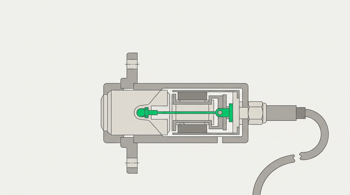
VW sensors infer the measured quantity from the change in resonant frequency of a tensioned wire. The vibrating frequency is converted into engineering units through calibration coefficients, with temperature compensation commonly provided through an additional thermistor or an integrated temperature channel. VW technology has a long record in embedded and remote geotechnical instrumentation, including piezometers, strain gauges, load cells, crack meters and extensometers.
MEMS sensors use micro-machined capacitive, piezoresistive or inertial structures. A MEMS inclinometer measures changes in gravity relative to its sensing axes; an accelerometer measures dynamic motion. Digital signal processing can provide filtering, temperature compensation, event detection and network integration. MEMS is attractive when compact dimensions, multi-axis sensing, frequent sampling or direct digital communication are required.
The practical VW vs MEMS decision depends on the measurand. A VW piezometer and a MEMS inclinometer are not interchangeable simply because both produce digital output through a datalogger. They observe different physical quantities. A MEMS tilt sensor may identify rotation of a retaining wall, while a VW piezometer identifies hydraulic response behind it. In a complete instrumentation scheme, both may be necessary.
For a broader treatment, engineers can review vw vs mems sensors and then assess whether the project needs static stability, dynamic response, distributed measurement or a combination.
Three-way geotechnical sensor comparison for procurement
The table below compares the three technology families at system level. It is not a substitute for a model-specific data sheet, calibration certificate or installation method statement. Values such as accuracy, range and operating temperature must be accepted only from the proposed instrument’s technical submittal.
| Evaluation criterion | Vibrating wire | MEMS | Fibre optic |
|---|---|---|---|
| Primary measurement principle | Resonant frequency of a tensioned wire | Micro-machined inertial, capacitive or resistive element | Change in optical wavelength, phase or backscatter |
| Typical geotechnical uses | Pore pressure, strain, load, settlement and crack movement | Tilt, acceleration, vibration and compact displacement systems | Strain, temperature, distributed deformation and long-route sensing |
| Static measurement suitability | Strong for long-duration trend monitoring | Strong when drift and temperature compensation are controlled | Strong, subject to interrogator stability and installation quality |
| Dynamic measurement suitability | Usually limited by readout and sampling configuration | Well suited to higher sampling rates and transient events | Possible, but dependent on interrogator type, bandwidth and sensor design |
| Electromagnetic interference | Electrical cabling requires appropriate shielding and grounding practice | Electrical and digital interfaces require EMC controls | Optical sensing is intrinsically immune along the fibre route |
| Multiplexing | Supported through suitable multiplexers and dataloggers | Supported through digital buses or network architecture | High channel density is possible through optical interrogation |
| Field installation | Established methods, but cable protection, grouting and saturation are critical | Orientation, mounting stiffness and axis alignment are critical | Fibre routing, bend radius, splicing and protection require specialist control |
| Power and communications | Often suitable for periodic excitation and low-power remote logging | Requires stable electrical power and compatible digital communication | Interrogator generally requires planned power, enclosure and communications |
| Key procurement risk | Temperature effects, cable damage, poor saturation or incorrect calibration factors | Bias drift, cross-axis response, magnetic or thermal effects and unsuitable sampling | Fibre breakage, connector loss, interrogator dependency and installation damage |
| Best selection basis | Stable long-term engineering quantities with established calibration workflows | Compact multi-axis or dynamic measurements with digital integration | Long-distance, EMI-sensitive, multiplexed or distributed strain applications |
Accuracy, resolution, drift and environmental effects
Accuracy and resolution are different procurement parameters. Resolution describes the smallest reported increment; accuracy describes closeness to the true value under stated conditions. A system can display 0.001 units while its overall uncertainty is much larger because of calibration, temperature, installation, reference movement, signal conditioning and conversion.
For VW devices, review the calibration polynomial, frequency range, temperature coefficient, zero stability, excitation method and cable resistance limits. A pressure transducer should be evaluated over its actual pressure range rather than its nominal full scale. A narrow-range instrument may provide better practical sensitivity for a low-pressure application, provided the maximum credible pressure and installation transients remain within limits.
For MEMS devices, examine bias instability, repeatability, noise density, non-linearity, hysteresis, cross-axis sensitivity and temperature compensation. Tilt readings can be affected by mounting stress, local vibration and changes in the sensor reference frame. Accelerometer specifications should distinguish measurement bandwidth from sample rate; a high sample rate does not automatically provide useful dynamic information.
For fibre optic instruments, review wavelength resolution, gauge length, strain transfer, optical loss budget, connector performance and temperature-strain separation. Bragg-grating systems may require a temperature sensor or compensation model. Distributed systems require careful interpretation of spatial resolution, gauge length and event localisation.
In all three cases, the acceptance plan should include zero checks, temperature checks where practicable, channel identification, calibration traceability and verification after installation. The data sheet should state whether quoted performance is for the sensing element, the complete sensor, or the sensor-plus-interrogator chain.
Installation and survivability in Indian construction conditions
Construction conditions often dominate sensor performance. Instruments may be exposed to monsoon water, cement slurry, grout pressure, dust, welding currents, accidental impact, electromagnetic sources, temperature cycles and temporary access constraints. A sensor selected in the design office can become unusable if the installation detail does not preserve its reference point or load path.
For VW piezometers, saturation and de-airing are essential where the instrument uses a porous filter. The filter grade must suit the soil and hydraulic response required. Cable splices, conduit entries and junction boxes need water protection. In embankments and excavations, the installation record should identify chainage, elevation, orientation, borehole details, grout or filter material and baseline reading.
MEMS tilt instruments need a stiff, stable mounting surface. A poorly fixed bracket can measure bracket deformation rather than structural rotation. The method statement should control orientation, fastening torque, datum survey, thermal exposure and commissioning time. If the system is intended to capture vibration, installation must also avoid unintended resonances.
Fibre optic cables require minimum bend radius, protected transitions, suitable strain transfer and inspection of connectors or splices. The route should be coordinated with reinforcement, formwork, waterproofing, drainage and access provisions. Fibre is not automatically damage-proof; its advantage is immunity to electromagnetic interference, not immunity to crushing or excessive bending.
These requirements are relevant to high-rise settlement monitoring at L&T Constructions Noida Realty Green, Sector-120, where sensor analytics and construction coordination must support building and foundation decisions. They also apply to bridge monitoring accessories supplied for IIT-Mandi, although the measurands and exposure conditions differ.
Data acquisition, telemetry and alarm logic
A sensor is only one part of an SHM channel. The complete chain includes excitation or interrogation, signal conditioning, datalogging, time synchronisation, communications, storage, visualisation and alarm management. Procurement should therefore specify system performance, not only the transducer model.
VW channels require compatible excitation and frequency measurement. The datalogger should preserve raw readings or frequency values, engineering-unit conversion coefficients, temperature channels and timestamps. MEMS systems may communicate through analogue, serial, CAN, Modbus or other interfaces; protocol ownership and cybersecurity responsibilities must be clear. Fibre optic systems require interrogator capacity, optical channel allocation, network availability and a plan for loss-of-signal conditions.
Sampling must match the physical process. Monthly settlement trends do not need the same sampling architecture as traffic-induced bridge vibration. Conversely, a slowly sampled system can miss transient events and create false confidence. The monitoring specification should state scan interval, recording interval, event-trigger logic, data retention, synchronisation accuracy and acceptable communication outage.
Alarm thresholds should include warning and action levels, persistence periods, rate-of-change checks and validation against adjacent channels. For example, a sudden change in pore pressure should be reviewed alongside rainfall, pumping, excavation stage and nearby deformation. Automated alerts assist the engineer; they do not replace interpretation.
Geolook’s geotechnical dataloggers and data acquisition systems should be evaluated as part of this complete chain. For transport assets, the transport infrastructure monitoring framework provides a relevant context for integrating field channels with inspection and reporting workflows.
Lifecycle cost and technical submittal requirements
Initial sensor price is an incomplete basis for procurement. Lifecycle cost includes installation labour, calibration, junction boxes, cable or fibre protection, multiplexers, interrogators, dataloggers, power systems, communication charges, inspection access, spares, recalibration and data management. A lower unit price can create a higher project cost when installation or commissioning is complex.
Request a technical submittal that identifies the sensing element, complete operating range, stated accuracy, resolution, repeatability, hysteresis, temperature range, ingress protection, materials, cable length limits, connector type, calibration method and expected service conditions. Require a channel schedule showing sensor ID, location, measurand, unit, range, baseline, trigger levels and associated response.
For all technologies, ask how failed channels are diagnosed. Can the system distinguish sensor failure, cable damage, power loss, communication loss and a genuine engineering change? Can a replacement channel inherit the correct calibration coefficients and metadata? Are raw data and processed data exportable in a documented format?
For government, railway and highway works, the procurement file should preserve approval drawings, inspection and test plans, calibration certificates, installation photographs, commissioning records and as-built coordinates. References to IRC SP-35, IRC SP-37, IRC:6, IRC:78, IRC:112 or IRC:114 may apply to bridge-related schemes; the governing contract and authority requirements remain controlling.
For a wider comparing sensor technologies for structural health monitoring india framework, map every proposed channel to a decision, an installation detail and a responsible reviewer before issuing the purchase order.
A practical selection workflow for consultants
- Define the engineering question. State whether the objective is to detect settlement, pore-pressure response, tilt, strain, crack movement, vibration or distributed deformation.
- Set the measurement envelope. Establish expected range, resolution, accuracy, sampling rate, temperature range and credible overload conditions in mm, kPa, micro-strain, degrees or mm/s2.
- Assess the site. Record groundwater, soil type, excavation sequence, access, cable route, electromagnetic sources, rainfall exposure, traffic, seismic demand and construction interfaces.
- Choose the technology family. Use VW where stable long-term scalar measurements and established field practice dominate; MEMS where compact multi-axis or dynamic data are needed; fibre optic where optical immunity, multiplexing or distributed measurement justifies the interrogator architecture.
- Design the channel. Select sensors, mounting, cabling, junctions, power, dataloggers, communications and software as one system.
- Verify performance. Conduct factory acceptance tests, calibration review, installation inspection, zero checks and commissioning against approved baselines.
- Define the response plan. Assign warning and action thresholds, review frequency, escalation route, data backup and maintenance responsibility.
This workflow prevents a common error in a geotechnical sensor comparison: treating technology selection as a product ranking instead of a measurement-system design decision.
Where each technology is usually the better fit
VW is often the practical choice for long-term pore-pressure, load, strain and displacement monitoring where the project team has established installation and readout procedures. It is especially useful when the data requirement is a stable engineering trend over construction stages or service life.
MEMS is often preferable for tilt arrays, compact inclinometers, acceleration and vibration measurements, or systems that require digital networking and frequent scans. Its selection must include a clear plan for bias, temperature and mounting verification.
Fibre optic sensing becomes attractive where electromagnetic interference, long cable routes, high channel density, distributed strain or electrical isolation is a significant design concern. It should be selected with an interrogator, optical budget, protection detail and specialist commissioning plan—not as an isolated sensor purchase.
Hybrid systems can be technically appropriate. A deep excavation may combine VW piezometers, MEMS tilt nodes and survey prisms. A bridge may combine strain, acceleration, displacement and temperature channels. The decision should be governed by the failure mechanism and required evidence, not by a preference for one technology.
Frequently Asked Questions
Q: Which sensor technology is best for geotechnical monitoring?
A: No sensor technology is best for every geotechnical monitoring application. VW sensors commonly suit stable measurements of pore pressure, strain, load and displacement; MEMS suits tilt, acceleration and compact digital networks; fibre optic systems suit EMI-sensitive, multiplexed or distributed strain applications. Selection should follow the measurand, range, environment, sampling requirement and installation method.
Q: What is the main difference between VW and MEMS sensors?
A: The main difference between VW and MEMS sensors is their measurement principle and typical application profile. VW instruments derive readings from resonant frequency changes in a tensioned wire, while MEMS instruments use micro-machined electrical or inertial elements. VW is widely used for stable static geotechnical quantities; MEMS is often chosen for tilt, acceleration, multi-axis sensing and digital integration.
Q: Are fibre optic sensors suitable for Indian infrastructure projects?
A: Fibre optic sensors are suitable for Indian infrastructure projects when their installation and interrogation requirements are properly engineered. They can tolerate electromagnetic interference along the optical route and support multiplexed or distributed measurements. Designers must still control bend radius, strain transfer, connector protection, optical loss, temperature compensation, power, communications and specialist commissioning.
Q: What should a geotechnical sensor procurement specification include?
A: A geotechnical sensor procurement specification should define the measurand, range, accuracy, resolution, repeatability, temperature effects, sampling rate, environmental rating, calibration traceability, mounting, cable or fibre requirements, datalogger interface, communication protocol, data format, acceptance tests and maintenance responsibilities. It should also identify baseline readings, trigger levels, channel metadata and the procedure for replacing failed instruments.
Q: Can VW, MEMS and fibre optic sensors be used together?
A: VW, MEMS and fibre optic sensors can be used together when each channel addresses a defined engineering question. For example, VW piezometers can track pore pressure, MEMS instruments can measure wall tilt, and fibre optic gauges can observe strain along a protected route. Integration requires compatible acquisition hardware, time synchronisation, common metadata, calibrated units and coordinated alarm logic.
Get tech recommendation
A defensible sensor decision begins with the monitoring objective, not a preferred product category. Share the structure type, soil and groundwater conditions, construction stage, measurands, expected ranges, sampling needs, access constraints and reporting requirements. Geolook can help develop a vendor-neutral architecture covering sensors, installation, dataloggers, communications, baselines and alarm workflows.
For a project-specific review of VW, MEMS and fibre-optic options, contact the Geolook engineering team through request a geotechnical sensor technology recommendation. Include drawings, instrumentation schedules and any applicable NHAI, RVNL, RITES, BRO, IRC or project specifications so the recommendation can be evaluated against the actual site conditions.
Project inquiry
Talk to a Geolook™ specialist
Share your monitoring requirement and our team will help identify the right next step.
By submitting, you agree that Geolook™ may contact you about this inquiry. Your details are not added to a marketing list.