VW vs MEMS Sensors: Which Technology Fits Your Project?
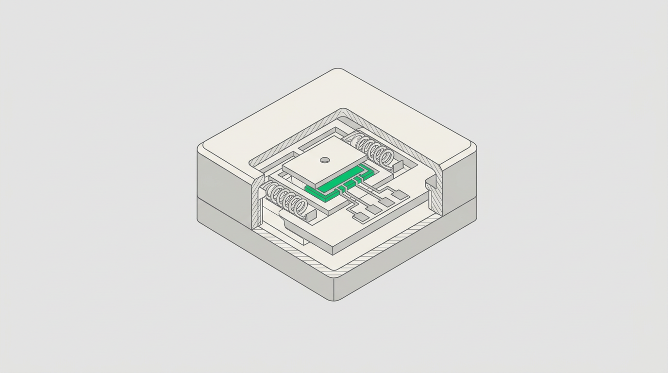
In August 2018, the Majerhat Bridge in Kolkata collapsed, killing three people and injuring dozens — a structure that had been flagged for inspection years earlier but lacked continuous embedded monitoring. The incident sharpened regulatory focus on real-time sensor-based structural health monitoring across India's ageing and new-build infrastructure alike. When specifying that monitoring, the first technical fork in the road is almost always the same: VW vs MEMS sensors. The choice is not cosmetic. It determines measurement resolution, long-term drift behaviour, power budget, data acquisition architecture, and ultimately whether your monitoring system will still be delivering reliable readings five years after commissioning.
This post provides a structured decision framework — grounded in physical performance parameters, Indian Standard requirements, and real deployment contexts — to help consulting engineers and procurement leads select the right transducer technology for their specific application.
Key Takeaways
- Vibrating wire (VW) sensors offer superior long-term stability and low drift, making them the default choice for embedded, inaccessible installations such as dam bodies, tunnel linings, and cast-in-place concrete.
- MEMS (Micro-Electro-Mechanical Systems) sensors offer higher dynamic bandwidth, lower unit cost, and compact form factor, making them well-suited for dynamic structural response, seismic event capture, and dense sensor arrays.
- The vw vs mems sensors decision is rarely binary — hybrid deployments combining both technologies are increasingly common on large infrastructure projects.
- Indian Standards IS 1893 (seismic), IRC SP-35 (bridge monitoring), and CWC dam safety guidelines each imply different sensor performance thresholds that should drive technology selection.
- Total cost of ownership, not unit price, is the correct procurement metric: VW systems carry higher per-channel hardware cost but lower long-term recalibration burden; MEMS arrays carry lower hardware cost but require more rigorous signal conditioning and drift correction protocols.
What Are Vibrating Wire and MEMS Sensors?
A vibrating wire (VW) sensor measures strain, pressure, displacement, or load by detecting the resonant frequency of a tensioned steel wire; because frequency is an inherently stable electrical signal, VW sensors exhibit very low zero drift over multi-year deployments, typically within ±0.1% full scale per year under stable temperature conditions. A MEMS sensor uses micro-fabricated silicon structures — accelerometers, gyroscopes, or pressure diaphragms etched at the micron scale — to transduce physical quantities into electrical signals, offering bandwidths from DC to several hundred Hz and enabling dynamic measurement that VW technology cannot achieve.
Understanding this fundamental difference in operating principle is the starting point for any rigorous sensor comparison SHM exercise. For a broader taxonomy of transducer types used across Indian infrastructure projects, see our overview of SHM sensor types comparison.
Operating Principles and Signal Characteristics
VW sensors excite the wire electromagnetically and measure the return frequency using a readout module or datalogger. The output is a frequency in Hz — or more commonly reported as a frequency-squared value (digits) — which is then converted to engineering units via a calibration factor supplied by the manufacturer. Because frequency measurement is largely immune to lead wire resistance variation and moderate electromagnetic interference, VW sensors perform reliably over cable runs exceeding 500 m, a practical necessity on large dam or tunnel projects.
MEMS sensors output an analogue voltage or, in newer designs, a digital signal over I²C, SPI, or RS-485. Their sensitivity is expressed in mV/g for accelerometers or mV/kPa for pressure variants. High-end MEMS accelerometers used in structural monitoring achieve noise floors below 1 µg/√Hz, enabling detection of ambient vibration amplitudes in the range of 0.01–0.1 mm/s² — sufficient for operational modal analysis on bridges and high-rise frames. However, MEMS sensors are susceptible to temperature-induced zero-offset drift, which must be compensated either in firmware or through periodic field calibration.
For the data acquisition layer that reads both sensor types, explore Geolook's structural monitoring dataloggers designed for multi-channel VW and MEMS integration.
VW vs MEMS Sensors: Head-to-Head Performance Comparison
The table below compares the two technologies across the parameters most relevant to Indian infrastructure monitoring projects. Values are representative of industrial-grade instruments used in civil SHM applications.
| Parameter | Vibrating Wire (VW) | MEMS |
|---|---|---|
| Measurement quantities | Strain, pore pressure, earth pressure, load, displacement, tilt (static) | Acceleration, tilt, displacement (dynamic & static), pressure |
| Frequency response | DC to ~1 Hz (quasi-static only) | DC to 200–2000 Hz depending on model |
| Long-term zero drift | Very low; typically <0.1% FS/year | Moderate to high without compensation; 0.5–2% FS/year typical for consumer-grade; <0.1% FS/year for industrial-grade with temperature correction |
| Resolution | 0.025% FS typical for strain gauges; 0.01 kPa for piezometers | Sub-µg for accelerometers; 0.001° for MEMS tiltmeters |
| Cable run tolerance | Excellent; >500 m with standard shielded cable | Limited for analogue output; digital variants (RS-485) support longer runs |
| Power consumption | Very low; µA-level during sleep, mA during excitation | Low to moderate; continuous-power variants draw 5–50 mA |
| Dynamic event capture | Not suitable; aliasing risk above 1 Hz | Suitable; captures seismic, blast, traffic-induced vibration |
| Embeddability in concrete | Excellent; purpose-built embedment gauges available per IS 13311 | Limited; vibration and curing heat can affect MEMS die bonding |
| Typical unit cost (INR, indicative) | ₹8,000–₹40,000 per channel depending on type | ₹2,000–₹25,000 per channel depending on grade |
| Calibration interval | Factory calibration typically valid 2–5 years; field verification simple | Requires periodic zero-offset correction; temperature characterisation needed |
This vibrating wire vs MEMS comparison makes clear that neither technology dominates across all parameters. The decision must be driven by the measurement objective, the installation environment, and the required service life.
Application-Specific Decision Framework for Indian Projects
The following framework maps common Indian infrastructure monitoring scenarios to the preferred sensor technology, drawing on the performance parameters above and the relevant Indian Standards or agency guidelines.
Dams and reservoirs (CWC guidelines, Dam Safety Act 2021): Pore pressure monitoring in embankment dams and uplift pressure monitoring in concrete gravity dams are classic VW piezometer applications. The Dam Safety Act 2021 mandates instrumentation for all large dams; CWC guidelines specify continuous monitoring of seepage, pore pressure, and deformation. Long cable runs, inaccessible installation points, and multi-decade service life requirements all favour VW technology. MEMS accelerometers may supplement VW arrays for seismic event recording.
Bridges (IRC SP-35, IRC:6, IRC:114): Static strain monitoring of girders, bearings, and piles suits VW strain gauges. Dynamic load assessment — traffic-induced vibration, wind response, and operational modal analysis — requires MEMS accelerometers with sampling rates of 100–1000 Hz. IRC:114 (cable-stayed and suspension bridges) implicitly requires dynamic response data that only MEMS can provide. Geolook supplied bridge health monitoring accessories to IIT-Mandi, where the instrumentation scope included both static and dynamic measurement channels, reflecting this hybrid requirement.
High-rise buildings and deep excavations (IS 1892, IS 13920): Settlement monitoring of raft foundations and retaining structures uses VW settlement cells and piezometers. Seismic response monitoring of the superstructure under IS 1893 zone requirements uses MEMS accelerometers. At L&T Constructions Noida Realty Green, Sector-120, Geolook deployed integrated sensor analytics combining static settlement monitoring with structural response channels — a practical example of the hybrid approach in a high-rise EPC context.
Tunnels (NATM, IS 14458): Convergence monitoring, rock bolt load cells, and shotcrete stress cells in NATM tunnels are overwhelmingly VW-based, given the harsh environment, long cable runs, and need for stable quasi-static readings over the construction period. MEMS vibration sensors may be added for blast monitoring during drill-and-blast excavation.
Slopes and embankments (IS 14458, NDMA guidelines): Inclinometers — whether manual or in-place — use either VW or MEMS tilt sensors. In-place inclinometer (IPI) strings increasingly use MEMS MEMS tilt sensors for their lower cost per node and digital bus compatibility, provided temperature compensation is implemented. For a detailed treatment of geotechnical sensor selection, see our geotechnical sensor comparison guide.
Signal Conditioning, Data Acquisition, and Integration Considerations
Sensor technology selection cannot be separated from the data acquisition architecture. VW sensors require a frequency-domain readout — either a dedicated VW readout unit or a datalogger with a built-in VW interface that sweeps the excitation frequency and measures the resonant response. Modern VW dataloggers digitise the frequency to a resolution of 0.01 Hz, translating to strain resolution of approximately 0.1 microstrain for a standard embedment gauge with a gauge factor of 3.5 Hz²/microstrain.
MEMS sensors with analogue output require a high-resolution ADC (typically 16–24 bit) with appropriate anti-aliasing filters. For dynamic applications, the Nyquist criterion requires a sampling rate at least twice the highest frequency of interest; for seismic monitoring per IS 1893, capturing the dominant frequency content of ground motion (typically 0.1–10 Hz) requires a minimum sampling rate of 20 Hz, though 100–200 Hz is standard practice to preserve waveform fidelity.
Digital MEMS sensors (I²C, SPI, RS-485 Modbus) simplify integration but introduce latency and synchronisation challenges in multi-node arrays. Time-stamping accuracy to within 1 ms is required for meaningful cross-correlation between spatially separated sensors — a requirement that demands GPS-disciplined or NTP-synchronised dataloggers.
Explore the full range of Geolook structural monitoring sensors compatible with both VW and MEMS acquisition architectures.
Total Cost of Ownership: Beyond Unit Price
Procurement decisions based on unit sensor price alone routinely produce monitoring systems that underperform or fail prematurely. A rigorous total cost of ownership (TCO) analysis for vw vs mems sensors must account for the following cost centres over the intended monitoring period:
- Hardware: VW sensors carry higher per-channel cost for strain and pressure measurement. MEMS accelerometers are lower cost per channel but may require more channels to achieve equivalent spatial coverage for dynamic monitoring.
- Installation: VW embedment gauges require careful placement during concrete pours; MEMS surface-mount sensors are faster to install but require rigid, vibration-isolated mounting surfaces to avoid spurious readings.
- Cabling and connectors: VW systems use standard shielded twisted-pair cable (low cost); MEMS analogue systems require screened cable with impedance matching; digital MEMS systems require data-grade cable with correct termination.
- Datalogger channels: VW channels are typically more expensive per channel on the datalogger than analogue input channels for MEMS, but VW channels can be multiplexed at lower scan rates without data loss.
- Calibration and maintenance: VW sensors are inherently stable and require minimal field recalibration. MEMS sensors, particularly tiltmeters and accelerometers in outdoor environments, require periodic zero-offset verification and temperature characterisation, adding to maintenance cost over a 5–10 year monitoring programme.
- Data storage and processing: High-frequency MEMS data (100–1000 Hz) generates substantially larger data volumes than quasi-static VW data (1 reading per 15 minutes typical), increasing storage, transmission, and processing costs.
For transport infrastructure projects where sensor selection intersects with long-term asset management, see how Geolook approaches transport infrastructure monitoring solutions.
Hybrid Deployments: When Both Technologies Are Specified
On complex infrastructure assets — long-span bridges, large dams, metro tunnels, and tall buildings in seismic zones — the monitoring specification increasingly calls for both VW and MEMS sensors in an integrated system. This is not redundancy; it is complementarity. VW sensors provide the stable, long-term baseline for static structural behaviour (settlement, strain accumulation, pore pressure trends), while MEMS sensors capture the dynamic response envelope (modal frequencies, damping ratios, seismic demand).
RITES Ltd engaged Geolook for a 3D Digital Twin and VR Visualisation Platform for Bridge Health Monitoring — a project where the data fusion layer ingested both quasi-static and dynamic sensor streams into a unified structural model. This kind of integrated deployment is becoming the reference standard for major Indian infrastructure assets, particularly as IRC SP-35 and the Dam Safety Act 2021 push towards continuous, automated monitoring rather than periodic manual inspection.
For a broader perspective on how different sensor technologies are deployed across Indian SHM projects, the post on comparing sensor technologies for structural health monitoring india provides additional application context.
Frequently Asked Questions
Q: What is the main difference between VW and MEMS sensors in structural health monitoring?
A: Vibrating wire sensors measure quasi-static quantities — strain, pressure, load — by detecting the resonant frequency of a tensioned wire, offering very low long-term drift. MEMS sensors use micro-fabricated silicon structures to measure dynamic quantities including acceleration and high-frequency vibration. The core difference is bandwidth: VW suits static monitoring; MEMS suits dynamic event capture up to several hundred Hz.
Q: Which sensor type is required for seismic monitoring under IS 1893?
A: IS 1893 seismic monitoring requires sensors capable of capturing ground motion and structural response across a frequency range of approximately 0.1–33 Hz, which mandates MEMS accelerometers. Vibrating wire sensors cannot sample at the rates required to resolve seismic waveforms. Industrial-grade MEMS accelerometers with noise floors below 1 µg/√Hz and sampling rates of 100–200 Hz are the standard specification for IS 1893-compliant structural monitoring.
Q: Can VW and MEMS sensors share the same datalogger?
A: Yes, modern multi-channel dataloggers support simultaneous VW frequency-domain inputs and analogue or digital MEMS inputs on the same unit, provided the datalogger has dedicated VW excitation and readout circuitry alongside high-resolution ADC channels for MEMS signals. Time-synchronisation between channels must be verified to within 1 ms for dynamic correlation analysis to be valid.
Q: How long do VW sensors last in embedded concrete applications?
A: Vibrating wire sensors embedded in concrete have demonstrated service lives exceeding 20 years in well-documented dam and bridge monitoring programmes, provided the cable terminations are protected from moisture ingress and the wire is not subjected to mechanical shock during concrete placement. This longevity is the primary reason VW remains the default technology for inaccessible, long-term embedded installations under CWC and IRC guidelines.
Q: What is the typical resolution of a MEMS tiltmeter compared to a VW tiltmeter?
A: A MEMS tiltmeter used in structural monitoring typically achieves a resolution of 0.001° to 0.005°, while a VW-based tiltmeter achieves approximately 0.01° to 0.025° resolution. MEMS tiltmeters offer finer angular resolution and faster update rates, but require rigorous temperature compensation to maintain accuracy over the full operating temperature range of −20°C to +70°C typical of Indian field conditions.
Get sensor recommendation
Selecting between VW and MEMS sensors — or specifying a hybrid system — requires matching transducer physics to your measurement objective, installation environment, data acquisition architecture, and total monitoring budget. A mismatch at the sensor selection stage propagates through every subsequent layer of the monitoring system and cannot be corrected without hardware replacement.
Geolook's instrumentation engineers work with consulting engineers and procurement teams across NHAI, RVNL, CWC, and EPC contractors to develop sensor specifications that are technically defensible and procurement-ready. Whether your project involves bridge health monitoring, deep excavation settlement, tunnel convergence, or seismic response of a high-rise frame, we can provide a written sensor recommendation with supporting technical rationale.
Contact Geolook for a project-specific sensor recommendation — bring your monitoring brief and we will return a structured sensor schedule with technology justification, channel count, and datalogger compatibility matrix.
Project inquiry
Talk to a Geolook™ specialist
Share your monitoring requirement and our team will help identify the right next step.
By submitting, you agree that Geolook™ may contact you about this inquiry. Your details are not added to a marketing list.