Inclinometer Sensors for Slope Stability in Hilly Terrain
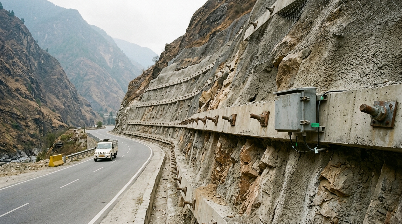
In August 2010, cloudbursts triggered a catastrophic landslide at Leh, Ladakh, killing over 200 people and destroying infrastructure across a 40 km corridor — a disaster that the National Disaster Management Authority (NDMA) later cited as evidence that hilly terrain in India demands continuous, instrument-based slope surveillance rather than periodic visual inspection. The Geological Survey of India (GSI) has mapped more than 0.49 million sq km of India as landslide-prone, covering the Himalayas, Western Ghats, and the North-East. Against this backdrop, selecting the correct inclinometer sensors for slope stability in hilly terrain is not a procurement detail — it is a life-safety and project-continuity decision.
This guide walks geotechnical engineers and EPC project managers through the three principal inclinometer technologies — borehole inclinometer, MEMS inclinometer slope sensors, and in-place inclinometers (IPI) — and provides a structured framework for matching sensor type to site conditions, displacement thresholds, and the monitoring obligations set out under IS 14458 and NDMA guidelines on landslides.
Key Takeaways
- Inclinometer sensors measure lateral displacement profiles within a borehole casing to detect sub-surface shear zones before surface failure becomes visible.
- IS 14458 and NDMA landslide guidelines require quantified displacement monitoring at high-risk cut slopes; alert thresholds are typically set at 5–10 mm cumulative displacement for early warning and 25–50 mm for evacuation triggers, depending on slope geometry and geology.
- Borehole inclinometers offer the highest vertical resolution for deep-seated failures; MEMS inclinometer slope sensors provide continuous automated data; IPI arrays deliver real-time profiling without manual probe traversal.
- Sensor selection must account for borehole depth, expected displacement rate (mm/day vs mm/month), data telemetry requirements, and the presence of active shear planes.
- For transport corridors in hilly terrain — NH-44, NH-58, NH-707 — MORTH and NHAI increasingly mandate automated slope monitoring as part of geotechnical instrumentation plans for EPC contracts.
What Is an Inclinometer Sensor for Slope Stability?
An inclinometer sensor for slope stability is a tilt-measuring device installed inside a grouted borehole casing that records angular deviation from vertical at discrete depth intervals, enabling engineers to calculate lateral displacement profiles and identify the depth and magnitude of sub-surface shear movement. The sensor responds to the deformation of the casing as the surrounding soil or rock mass displaces, translating angular change (in arc-seconds or milliradians) into linear displacement (mm) at each measurement depth.
In hilly terrain, where failure planes can develop anywhere from 1 m to 30 m below the slope surface, the borehole inclinometer remains the primary tool for locating the shear zone. IS 1892 governs sub-surface investigation for geotechnical purposes, and IS 14458 provides guidelines for retaining walls and cut slopes in hilly areas. Both codes implicitly require quantified deformation data that only instrument-based monitoring can supply.
Explore the full range of MEMS digital inclinometer sensors for slope and structural tilt monitoring to understand sensor specifications before selecting for a specific site.
Displacement Thresholds and Alert Levels for Hilly Terrain Slopes
Displacement thresholds are the quantitative limits at which monitoring data triggers a defined response — increased survey frequency, engineering review, or evacuation. NDMA guidelines on landslides recommend a three-tier alert framework for instrumented slopes:
- Green (Watch): Cumulative lateral displacement below 5 mm over the monitoring baseline period. No action beyond routine data logging.
- Amber (Alert): Cumulative displacement of 5–25 mm, or a displacement rate exceeding 1 mm/day sustained over 3 consecutive days. Engineering review required; increased monitoring frequency to hourly or continuous.
- Red (Evacuation): Cumulative displacement exceeding 25–50 mm, or a rate exceeding 5 mm/day. Immediate evacuation of the hazard zone and emergency geotechnical assessment.
These thresholds are indicative and must be calibrated to site-specific geology. A stiff over-consolidated clay slope may tolerate 10 mm before accelerating failure, while a colluvial debris slope on a Himalayan road cut may reach critical velocity at 3–4 mm cumulative displacement. The inclinometer casing itself has a physical limit: most standard ABS or aluminium casings with 70 mm or 85 mm outer diameter will shear and become unreadable beyond 50–75 mm of lateral displacement, which is why early-warning thresholds must be set well below this mechanical limit.
For a broader view of how displacement thresholds integrate into a complete monitoring programme, see our detailed guide on slope stability monitoring for cut slopes and embankments.
Borehole Inclinometer: Principles, Strengths, and Limitations
The conventional borehole inclinometer system consists of a grooved ABS or aluminium casing grouted into a borehole, a biaxial servo-accelerometer or MEMS probe lowered on a graduated cable, and a portable readout unit. The probe is traversed from the bottom of the casing to the top in 0.5 m increments, recording tilt in two orthogonal planes (A-axis along the anticipated displacement direction, B-axis perpendicular). Cumulative displacement is computed by integrating the sine of the tilt angle over each 0.5 m segment.
Borehole inclinometers are well-suited to:
- Deep-seated rotational or translational failures where the shear zone lies more than 5 m below the surface.
- Sites where the failure mechanism is not yet known and a full displacement profile is needed to locate the shear plane.
- Baseline characterisation surveys before automated sensors are installed.
Limitations include the requirement for manual probe traversal — typically once per week to once per month — which means the system cannot provide real-time data or trigger automated alerts. Borehole depths in Himalayan terrain commonly reach 15–30 m, and probe traversal in a 25 m casing takes approximately 45 minutes per reading. In active monsoon conditions, access to remote slope instrumentation points may be impossible for weeks at a time, creating data gaps precisely when displacement rates are highest.
Casing installation must follow IS 2720 (Part 1) site investigation procedures. The annular space between the casing and borehole wall should be grouted with a cement-bentonite mix matched to the stiffness of the surrounding soil to ensure the casing deforms compatibly with the ground.
MEMS Inclinometer Slope Sensors: Continuous Automated Monitoring
A MEMS inclinometer slope sensor uses micro-electromechanical system (MEMS) accelerometer elements to measure tilt continuously, transmitting data at user-defined intervals — typically every 15 minutes to 1 hour — to a data acquisition unit and cloud platform. Unlike the manual probe system, MEMS sensors are fixed at a single depth inside the casing or mounted on the slope surface, providing a continuous time-series of tilt at that point.
MEMS sensors are particularly effective when:
- The shear zone depth is already known from prior borehole inclinometer surveys or geological mapping.
- Automated alert generation is required for unmanned remote slopes on national highways or railway corridors.
- Solar-powered wireless telemetry is needed due to the absence of grid power — common in BRO-managed roads above 3,000 m elevation.
Resolution of modern MEMS inclinometer slope sensors is typically ±0.001° (approximately 0.017 mrad), with a measurement range of ±15° to ±30°. At a 10 m installation depth, a 0.001° resolution corresponds to approximately 0.17 mm lateral displacement resolution — sufficient for detecting the early creep phase of a translational slide. Temperature compensation is critical: uncompensated MEMS sensors can exhibit apparent tilt drift of 0.01–0.05° per 10°C change, which at 10 m depth translates to 1.7–8.7 mm of spurious displacement signal. Specify sensors with on-board temperature compensation and validate against a stable reference during commissioning.
For projects on transport corridors in hilly terrain, see how Geolook's slope and infrastructure monitoring solutions for transport corridors integrate MEMS sensors with real-time alert dashboards.
In-Place Inclinometer (IPI) Arrays: Real-Time Profiling
An in-place inclinometer (IPI) array consists of multiple MEMS or servo-accelerometer tilt sensors connected in a string and installed at fixed depths within a single borehole casing, providing a continuous displacement profile without manual probe traversal. Each sensor node in the string measures tilt at its specific depth; the array effectively replicates the manual probe survey in real time.
IPI arrays are the preferred solution when:
- The slope is in an active displacement phase and manual access is unsafe.
- Multiple shear zones exist at different depths — common in Himalayan debris-covered slopes with interbedded weak layers.
- The monitoring contract requires automated alert generation with sub-hourly data latency.
A typical IPI string for a 20 m borehole might include 8–10 sensor nodes at 2 m spacing, each with a resolution of ±0.001° and a range of ±10°. The string is connected to a datalogger at the surface via a single multi-conductor cable, reducing installation complexity compared to running separate cables for each sensor. Data is transmitted via GSM/4G or LoRa radio to a central server, where displacement profiles are reconstructed and compared against alert thresholds in near real time.
The principal limitation of IPI arrays is cost per borehole: a 10-node string with datalogger and telemetry represents a significantly higher capital outlay than a single MEMS sensor at a known shear zone. For slopes where the failure mechanism is well-characterised and only one or two shear planes are active, a targeted MEMS installation at the known shear depth is more cost-effective. IPI arrays are justified where the failure mechanism is complex or where the consequences of missed displacement are severe — for example, on slopes directly above a national highway or a railway line.
Learn about the full range of landslide monitoring instruments and sensor arrays available for hilly terrain deployments.
Comparison of Borehole Inclinometer, MEMS Inclinometer, and IPI for Slope Stability
| Parameter | Borehole Inclinometer (Manual Probe) | MEMS Inclinometer Slope Sensor (Fixed) | In-Place Inclinometer (IPI) Array |
|---|---|---|---|
| Displacement profile | Full depth profile at each survey | Single depth, continuous time-series | Full depth profile, continuous time-series |
| Data frequency | Weekly to monthly (manual) | Every 15 min to 1 hour (automated) | Every 15 min to 1 hour (automated) |
| Shear zone identification | Yes — best tool for unknown shear depth | No — requires prior knowledge of shear depth | Yes — detects multiple shear zones simultaneously |
| Typical resolution | ±0.02 mm per 0.5 m increment | ±0.17 mm at 10 m depth (0.001° MEMS) | ±0.17 mm per node at installed depth |
| Automated alert capability | No | Yes | Yes |
| Suitability for remote/unmanned sites | Low — requires site access | High — solar + wireless telemetry | High — solar + wireless telemetry |
| Applicable Indian Standard / guideline | IS 1892, IS 2720, IS 14458 | IS 14458, NDMA landslide guidelines | IS 14458, NDMA landslide guidelines |
| Relative capital cost per borehole | Low (probe shared across boreholes) | Low to medium (one sensor per borehole) | High (multi-node string per borehole) |
| Best application | Baseline surveys, shear zone location | Known shear zone, automated early warning | Complex failure mechanisms, critical infrastructure |
Sensor Selection Criteria for Hilly Terrain Projects
Selecting inclinometer sensors for slope stability in hilly terrain requires a structured decision process that accounts for geology, project phase, monitoring objectives, and site accessibility. The following criteria should be evaluated systematically:
- Failure mechanism and shear zone depth: If the shear zone is unknown, begin with manual borehole inclinometer surveys to establish the displacement profile. Once the shear zone is located, transition to fixed MEMS sensors or an IPI string for continuous monitoring. IS 14458 recommends that cut slopes steeper than 1V:1H in weak rock or soil be instrumented from the start of construction.
- Displacement rate: Slow creep (less than 1 mm/month) can be adequately captured by weekly manual surveys. Accelerating slopes (greater than 1 mm/day) require continuous automated monitoring with sub-hourly data latency to provide actionable early warning.
- Site accessibility and power availability: Remote Himalayan slopes above 2,500 m elevation may be inaccessible for 3–5 months during winter. Automated sensors with solar power, battery backup, and satellite or LoRa telemetry are the only viable option for year-round monitoring.
- Number of active shear planes: Slopes with a single well-defined basal shear plane are well-served by a targeted MEMS sensor at that depth. Slopes with multiple weak interbeds — common in the Siwalik Hills and Shillong Plateau — require IPI arrays to capture the full displacement profile.
- Regulatory and contractual obligations: NHAI and MORTH EPC contracts for hill roads increasingly specify automated geotechnical instrumentation with real-time data transmission to a project management unit. Verify the monitoring specification in the contract before finalising sensor type.
For a comprehensive overview of sensor types and installation methods across slope monitoring programmes, refer to our guide on slope instrumentation for cut slopes, embankments, and natural hillsides.
Installation, Commissioning, and Data Quality Assurance
Correct installation is as critical as sensor selection. A poorly grouted casing or a sensor installed in a borehole that does not penetrate below the failure plane will produce data that is either unrepresentative or uninterpretable. Key installation requirements for inclinometer sensors for slope stability in hilly terrain include:
- Borehole depth: The casing must extend at least 2–3 m below the deepest anticipated shear zone into stable, non-displacing material. This anchors the base of the measurement profile and provides a fixed reference for cumulative displacement calculations.
- Casing orientation: The A-axis grooves of the casing must be aligned with the anticipated direction of maximum displacement — typically the downslope azimuth. Misalignment by more than 5° introduces a cosine error that underestimates true displacement.
- Grout mix: Use a cement-bentonite grout with an unconfined compressive strength matched to the surrounding soil. Over-stiff grout in soft soil creates a stress concentration that can shear the casing prematurely; under-stiff grout allows the casing to move independently of the ground.
- Baseline readings: Take a minimum of three baseline traversals over 2–4 weeks before construction activities begin. Baseline variability greater than ±0.5 mm indicates either instrument error or early displacement and must be investigated before accepting the baseline.
- Data validation: Cross-check inclinometer displacement data against surface survey monuments (total station or GNSS) at the same slope section. Divergence between surface and sub-surface displacement vectors indicates either instrument error or a complex failure mechanism requiring re-evaluation.
To understand how inclinometer data integrates with surface monitoring and early warning systems, see our resource on best instruments for early landslide warning systems in hilly terrain.
Frequently Asked Questions
Q: What is the difference between a borehole inclinometer and an in-place inclinometer (IPI)?
A: A borehole inclinometer uses a portable probe manually traversed through a grouted casing to produce a displacement profile at the time of each survey, while an in-place inclinometer (IPI) consists of fixed sensors at multiple depths within the same casing, generating a continuous real-time displacement profile without manual intervention. IPI arrays are preferred for critical slopes requiring automated early warning.
Q: What displacement threshold should trigger an alert on a monitored slope in India?
A: NDMA landslide guidelines recommend an amber alert at cumulative lateral displacement of 5–25 mm or a sustained rate exceeding 1 mm/day, and a red alert at cumulative displacement of 25–50 mm or a rate exceeding 5 mm/day. These thresholds must be calibrated to site-specific geology, slope geometry, and the consequences of failure for the specific project.
Q: Can MEMS inclinometer slope sensors be used in freezing Himalayan conditions?
A: MEMS inclinometer slope sensors can operate in freezing conditions if specified with an extended temperature range, typically −40°C to +85°C for industrial-grade MEMS elements. On-board temperature compensation is mandatory to prevent apparent tilt drift caused by thermal expansion of the sensor housing and casing. Solar panels must be sized for reduced winter insolation at high-altitude Himalayan sites.
Q: Which Indian Standard governs inclinometer installation for cut slopes?
A: IS 14458 provides guidelines for retaining walls and cut slopes in hilly terrain and implicitly requires quantified deformation monitoring for high-risk slopes. IS 1892 governs sub-surface investigation procedures relevant to borehole siting and depth. NDMA guidelines on landslides provide the framework for alert thresholds and emergency response protocols for instrumented slopes in India.
Q: How many inclinometer boreholes are needed for a typical highway cut slope?
A: The number of inclinometer boreholes for a highway cut slope depends on slope length, geological variability, and failure risk. As a general practice aligned with IS 14458 and NDMA guidance, a minimum of one instrumented borehole per 50–100 m of slope length is recommended for high-risk cuts, with additional boreholes at geological discontinuities, drainage features, or locations of observed surface cracking.
View inclinometer specs
Geolook supplies borehole inclinometer casings, MEMS digital inclinometer sensors, and IPI arrays configured for hilly terrain deployments across India — from Himalayan highway cuts to Western Ghats rail embankments. Each system is specified to IS 14458 and NDMA displacement threshold requirements, with solar-powered wireless telemetry options for remote sites.
Download the Inclinometer Sensors for Slope Stability in Hilly Terrain Selection Guide for detailed sensor specifications, installation checklists, and alert threshold configuration templates. Review the complete MEMS digital inclinometer sensor specifications or contact Geolook's geotechnical instrumentation team to discuss sensor selection for your specific slope monitoring project.
Project inquiry
Talk to a Geolook™ specialist
Share your monitoring requirement and our team will help identify the right next step.
By submitting, you agree that Geolook™ may contact you about this inquiry. Your details are not added to a marketing list.