Geotechnical Monitoring of Landslide-Prone Slopes India
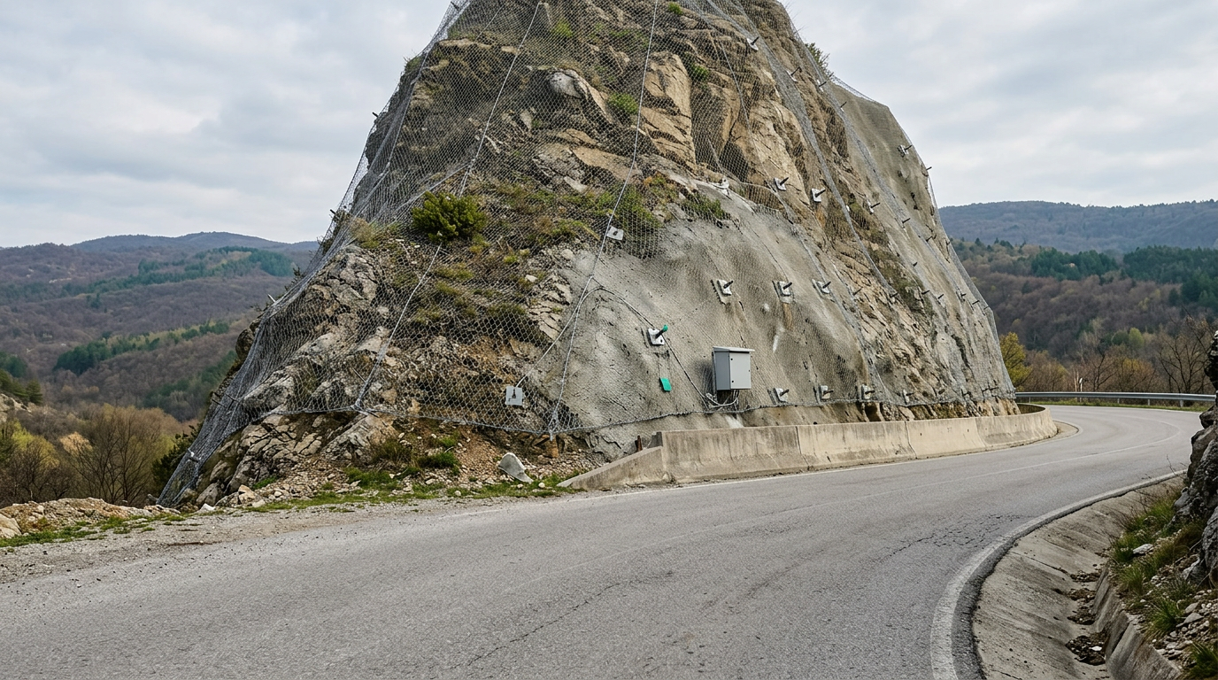
In August 2014, a series of cloudbursts triggered catastrophic landslides in Malin village, Pune district, Maharashtra, burying over 150 homes and killing more than 150 people — a disaster that the Geological Survey of India (GSI) subsequently attributed to a combination of lateritic soil saturation, pre-existing tension cracks, and the absence of any instrumented early warning system on the slope. That single event reshaped how Indian agencies think about geotechnical monitoring of landslide-prone slopes in India, accelerating the adoption of sensor-based surveillance across the Western Ghats, Himalayas, and North-East hill states.
India records among the highest landslide frequencies in the world. The GSI's National Landslide Susceptibility Mapping programme has delineated approximately 0.42 million sq km of landslide-prone terrain across 17 states and 4 union territories. For consultants and researchers designing monitoring programmes, the challenge is not merely selecting instruments — it is matching sensor type, sampling interval, and alert threshold to the specific failure mechanism and geological zone in question. This post provides a zone-wise technical framework for that task, grounded in GSI regional data, NDMA guidelines, and IS 14458.
Key Takeaways
- India's landslide-prone terrain spans roughly 0.42 million sq km across 17 states, per GSI's National Landslide Susceptibility Mapping programme — zone-specific monitoring design is therefore non-negotiable.
- IS 14458 (Parts 1–3) and NDMA's 2009 landslide guidelines provide the regulatory baseline for slope instrumentation and early warning thresholds in India.
- Failure mechanisms differ sharply by zone: rotational slides dominate Himalayan over-consolidated clays, debris flows are characteristic of the Western Ghats, and planar failures along foliation planes are typical in the North-East — each demands a different primary sensor.
- Piezometric head, subsurface displacement (inclinometry), and surface displacement (GNSS or total station) form the irreducible triad of any credible landslide monitoring programme.
- Real-time telemetry with automated threshold alerts, as recommended in NDMA guidelines, is the only configuration that provides actionable early warning — periodic manual readings are insufficient for rapidly moving slides.
What Is Geotechnical Monitoring of Landslide-Prone Slopes?
Geotechnical monitoring of landslide-prone slopes is the systematic, instrument-based measurement of subsurface and surface deformation, pore-water pressure, and environmental triggers on a slope to detect precursory movement, validate stability analyses, and activate early warning protocols before a failure event occurs.
The discipline draws on soil mechanics principles codified in IS 1892 and IS 2720, slope stability assessment methods referenced in IS 14458, and the hazard zonation frameworks published by GSI and NDMA. A monitoring programme typically integrates multiple sensor modalities — geotechnical, geodetic, and hydrometeorological — because no single instrument captures the full failure precursor chain. Pore-water pressure rise, for instance, may precede measurable displacement by hours to days on a slow-moving translational slide, while a debris flow may accelerate from creep to collapse within minutes.
For consultants designing such programmes, the starting point is always the GSI district-level landslide hazard zonation map and the site-specific geological investigation under IS 1892, which together define the probable failure mechanism and the critical monitoring parameters for that slope.
GSI Regional Mapping and Zone-Wise Hazard Classification
The GSI classifies India's landslide terrain into four broad physiographic zones, each with distinct lithology, rainfall regime, and dominant failure mode. Understanding this classification is prerequisite to any rational sensor deployment strategy.
Zone I — Himalayan and Trans-Himalayan Region: Encompasses J&K, Himachal Pradesh, Uttarakhand, and parts of Sikkim. Geology is dominated by highly fractured metamorphic and sedimentary sequences. Failure modes include deep-seated rotational slides in over-consolidated clays, rock falls along joint sets, and debris avalanches triggered by seismic events (IS 1893 Zone IV–V). Annual rainfall of 1,000–3,000 mm combined with snowmelt creates prolonged pore-pressure cycles. GSI's Landslide Hazard Zonation Atlas identifies over 66,000 landslide events historically recorded in this zone.
Zone II — North-East Hill States: Assam, Meghalaya, Nagaland, Manipur, Mizoram, Tripura, and Arunachal Pradesh. Highly weathered phyllites, schists, and sandstones with steep foliation dips create conditions for planar and wedge failures. Rainfall intensity regularly exceeds 100 mm/day during the southwest monsoon, and the Brahmaputra basin experiences frequent seismic activity. GSI's Bhuvan Landslide Atlas records this as the zone with the highest landslide density per unit area in India.
Zone III — Western Ghats and Konkan Coast: Kerala, Karnataka, Goa, and Maharashtra. Lateritic soils over basalt and gneiss are susceptible to shallow translational slides and debris flows when antecedent soil moisture reaches field capacity. The 2018 Kerala floods triggered over 2,300 landslides in a single monsoon season, per Kerala State Disaster Management Authority records. Failure depths are typically 1–5 m, making shallow piezometers and surface extensometers the primary instruments.
Zone IV — Eastern Ghats and Vindhyan Ranges: Lower hazard density but localised failures in cut slopes along NH corridors and mining areas. Monitoring here is largely project-specific rather than regional.
For slope stability monitoring to be effective, the instrument suite must be calibrated to the zone's dominant failure mechanism — a deep borehole inclinometer appropriate for Zone I may be unnecessary for a 3 m-deep lateritic slide in Zone III.
Core Instrument Suite for Landslide Monitoring India
Effective landslide monitoring India programmes deploy instruments across three measurement domains: subsurface deformation, pore-water pressure, and surface displacement. A fourth domain — hydrometeorological triggers — provides the causal context without which threshold alerts lack physical meaning.
Subsurface Deformation — Inclinometers: Borehole inclinometers measure lateral displacement profiles at depth intervals of 0.5 m, resolving the shear zone location to within ±0.1 mm per 25 m of casing under standard practice. MEMS-based digital inclinometers offer continuous in-place readings without manual probe traversal, enabling automated alert generation when displacement rate exceeds a defined threshold (commonly 1–2 mm/day for slow-moving slides). The MEMS digital inclinometer eliminates operator-dependent reading errors that affect traditional analogue probe systems. IS 14458 Part 2 recommends inclinometer installation at a minimum depth of 3 m below the inferred failure surface.
Pore-Water Pressure — Vibrating Wire Piezometers: Piezometric head is the most reliable precursor parameter for rainfall-triggered slides. Vibrating wire piezometers installed at the inferred failure plane measure pore pressure in kPa with a resolution of ±0.1 kPa. Alert thresholds are typically set at 70–80% of the critical pore pressure ratio (ru) derived from the limit equilibrium analysis. Standpipe piezometers remain acceptable for slow-response monitoring but are inadequate for real-time early warning.
Surface Displacement — GNSS and Robotic Total Stations: Continuous GNSS receivers provide 3D displacement vectors with sub-centimetre accuracy in post-processed mode. For slopes with dense vegetation or limited sky view, robotic total stations monitoring prism arrays at 15–30 minute intervals are preferred. Surface crack extensometers (wire or LVDT-based) provide high-resolution data at known tension crack locations.
Hydrometeorological Triggers — Rain Gauges and Soil Moisture Sensors: Tipping-bucket rain gauges with 0.2 mm resolution, co-located with the slope, enable rainfall intensity–duration threshold analysis per NDMA's 2009 guidelines. Volumetric soil moisture sensors at 0.3 m, 0.6 m, and 1.0 m depths track antecedent moisture conditions that modulate the rainfall threshold for failure initiation.
Explore the full range of landslide monitoring instruments and systems applicable to Indian geological conditions.
Instrument Selection by Failure Mechanism: A Comparative Framework
The table below maps dominant failure mechanisms — as classified by GSI zone — to the recommended primary and secondary instruments, measurement parameters, and relevant Indian standards. This structured mapping is the basis for a defensible monitoring design report.
| Failure Mechanism | Typical GSI Zone | Primary Instrument | Secondary Instrument | Key Parameter | Relevant Standard / Guideline |
|---|---|---|---|---|---|
| Deep rotational slide | Zone I (Himalayan) | In-place MEMS inclinometer array | Vibrating wire piezometer | Lateral displacement (mm), pore pressure (kPa) | IS 14458 Part 2, NDMA 2009 |
| Planar / wedge failure along foliation | Zone II (North-East) | Borehole inclinometer + crack extensometer | Continuous GNSS | Displacement vector (mm), crack aperture (mm) | IS 14458 Part 1, GSI Bhuvan Atlas |
| Shallow translational slide / debris flow | Zone III (Western Ghats) | Shallow piezometer (1–3 m depth) | Soil moisture sensor array | Pore pressure (kPa), volumetric water content (%) | IS 14458 Part 3, NDMA 2009 |
| Rock fall / toppling | Zone I, Zone II | Geophone / seismic sensor | Robotic total station on prism array | Ground vibration (mm/s²), displacement (mm) | IS 14458 Part 1 |
| Cut slope failure (highway / railway) | All zones — NH/SH corridors | In-place inclinometer + surface prism array | Vibrating wire piezometer | Lateral displacement (mm), pore pressure (kPa) | IS 14458, MORTH slope protection guidelines |
| Creep on natural slope | Zone I, Zone II | Continuous GNSS (24-hour epochs) | In-place inclinometer | Cumulative displacement (mm), displacement rate (mm/day) | IS 14458 Part 2, IS 1892 |
For transport infrastructure corridors — NH-44 through J&K, NH-10 in Sikkim, NH-37 in Assam — the MORTH slope protection guidelines and IRC provisions for hill roads supplement IS 14458 in defining minimum monitoring requirements. Geolook's geotechnical monitoring solutions for transport infrastructure address these corridor-specific requirements.
Monitoring Network Design: Spatial Density and Sampling Intervals
Network design translates the zone-wise hazard classification and failure mechanism analysis into a physical layout of instruments on the slope. Three parameters govern this design: spatial density of sensors, sampling interval, and telemetry architecture.
Spatial Density: IS 14458 Part 2 recommends a minimum of one inclinometer borehole per 50 m of slope width in the primary movement zone, with additional boreholes at the crown and toe. Piezometers should be installed at the failure plane depth and at mid-depth to capture the pressure gradient. For debris flow-prone slopes in Zone III, soil moisture sensors at a grid spacing of 20–30 m provide adequate spatial resolution for antecedent moisture mapping.
Sampling Intervals: The appropriate sampling interval depends on the expected velocity of movement. For slow-moving slides (velocity class 1–3 per Varnes classification, i.e., less than 1.6 m/month), daily or 6-hourly readings are adequate. For moderate to rapid slides (velocity class 4–5, 1.6 m/month to 1.8 m/hour), continuous sampling at 1–15 minute intervals with automated alert generation is required. NDMA's 2009 guidelines specify that early warning systems must be capable of issuing alerts with a minimum lead time of 30 minutes for evacuation to be feasible.
Telemetry Architecture: Remote slopes in Himalayan and North-East zones frequently lack GSM coverage. In such locations, satellite telemetry (VSAT or Iridium SBD) or LoRaWAN mesh networks provide the communication backbone. Data loggers must be rated for the ambient temperature range — down to −20°C in high-altitude Himalayan sites — and must support solar power with battery backup for a minimum of 72 hours of autonomous operation.
Alert Threshold Setting: Thresholds are set at three levels: yellow (watch), orange (warning), and red (evacuation), consistent with NDMA's multi-level alert protocol. For inclinometers, typical thresholds are: yellow at 5 mm cumulative displacement, orange at 10 mm, and red at 20 mm or a displacement rate exceeding 2 mm/hour. Piezometric thresholds are derived from the site-specific ru value at which the factor of safety (FS) drops below 1.2 in the limit equilibrium model.
Regulatory Framework: IS 14458, NDMA Guidelines, and GSI Mandates
The regulatory landscape for geotechnical slope monitoring in India is defined by three overlapping frameworks, each with distinct scope and authority.
IS 14458 (Parts 1–3): Published by the Bureau of Indian Standards, IS 14458 covers retaining walls and slope protection works. Part 1 addresses guidelines for selection of plants for erosion control; Part 2 covers design of retaining/breast walls; Part 3 addresses guidelines for landslide zonation mapping. While IS 14458 does not prescribe specific instrument types, it establishes the geotechnical investigation requirements (cross-referenced to IS 1892 and IS 2720) that form the basis of any monitoring design. Consultants preparing DPRs for slope stabilisation works on NH corridors are expected to demonstrate compliance with IS 14458 in the geotechnical investigation chapter.
NDMA Guidelines on Landslides (2009): The National Disaster Management Authority's guidelines provide the most operationally specific framework for landslide early warning in India. They define the minimum sensor suite for a community-level early warning system, specify the three-tier alert protocol (watch–warning–evacuation), and mandate integration with district disaster management plans. For consultants working on World Bank or ADB-funded slope stabilisation projects in India, NDMA compliance is typically a loan covenant condition.
GSI Landslide Susceptibility and Hazard Zonation: GSI's district-level hazard zonation maps, available through the Bhuvan geoportal, classify slopes into five hazard categories (very low to very high). These maps are the statutory reference for land-use planning under the Disaster Management Act 2005 and are increasingly cited in environmental impact assessments for linear infrastructure projects. Researchers should note that GSI's mapping is at 1:50,000 scale — site-specific investigations at 1:5,000 or larger scale are required for instrument placement design.
For a broader treatment of instrumentation selection across slope types, the guide on slope instrumentation covers sensor specifications, installation procedures, and data interpretation in detail.
Data Interpretation and Failure Precursor Recognition
Raw sensor data acquires engineering meaning only through systematic interpretation against the site's geomechanical model. Three precursor patterns are consistently documented in the literature on monitored landslides and are directly relevant to Indian conditions.
Accelerating Displacement (Inverse Velocity Method): Fukuzono's inverse velocity method, widely applied in open-pit mining and natural slope monitoring, plots the reciprocal of displacement rate against time. A linear trend toward zero inverse velocity indicates impending failure. This method has been validated on Himalayan slides where displacement data were available from inclinometers and GNSS. The method requires a minimum of 5–7 data points in the accelerating phase to produce a reliable failure time estimate.
Pore Pressure Threshold Exceedance: On rainfall-triggered slides, piezometric head typically rises sharply 6–24 hours after peak rainfall intensity. When the measured pore pressure ratio ru approaches the critical value derived from the limit equilibrium analysis (commonly ru = 0.3–0.5 for Himalayan residual soils), the slope is at or near the FS = 1.0 condition. Automated threshold alerts at ru = 0.7 × ru_critical provide the required lead time for evacuation.
Crack Propagation Patterns: Extensometer data showing accelerating crack aperture at the crown, combined with heave at the toe measured by surface settlement points, is a classic precursor to rotational failure. IS 14458 Part 2 recommends that crack widths exceeding 50 mm at the crown trigger immediate geotechnical review.
Researchers interested in the full instrumentation stack for early warning should consult the detailed guide on best instruments for early landslide warning systems, which covers sensor specifications, detection limits, and integration with alert dissemination platforms.
Geotechnical Slope India: Special Considerations for Cut Slopes on NH Corridors
Cut slopes on national highway corridors represent a distinct monitoring challenge within the broader geotechnical slope India context. Unlike natural slopes, cut slopes are anthropogenically destabilised — the act of excavation removes lateral support, reduces effective stress, and exposes fresh rock or soil to weathering and pore-pressure cycles. MORTH's guidelines for hill road construction and IRC SP-48 (Hill Road Manual) specify minimum slope angles for different rock mass classifications, but monitoring requirements for post-construction surveillance are less prescriptively defined.
On NH-44 (Jammu–Srinagar–Leh corridor), NH-58 (Rishikesh–Badrinath), and NH-10 (Siliguri–Gangtok), cut slope failures are among the most frequent causes of road closure during monsoon. The typical failure sequence involves: (1) rainfall infiltration through tension cracks behind the cut face, (2) pore pressure build-up in the weathered zone above the cut bench, (3) progressive shear failure along the weathered–fresh rock interface, and (4) debris deposition on the carriageway.
A monitoring programme for a cut slope on these corridors should include: inclinometers at 15–20 m spacing along the cut face, vibrating wire piezometers at the weathered–fresh rock interface, surface prism arrays on each bench monitored by robotic total station, and a tipping-bucket rain gauge with 15-minute data transmission. Alert thresholds should be integrated with the NHAI/MORTH road weather information system where available.
For researchers studying the interaction between slope instrumentation and transport network resilience, the post on what instruments are used to detect early signs of slope instability and landslides provides a comparative analysis of sensor performance under Indian field conditions.
Frequently Asked Questions
Q: What is the primary Indian standard governing geotechnical monitoring of landslide-prone slopes?
A: IS 14458 (Parts 1–3), published by the Bureau of Indian Standards, is the primary standard governing slope protection and landslide zonation in India. It is supplemented by NDMA's 2009 Landslide Guidelines, which specify early warning system requirements, and by IS 1892 and IS 2720 for the geotechnical site investigation that underpins any monitoring design.
Q: How does GSI's landslide hazard zonation map inform instrument placement on a slope?
A: GSI's district-level hazard zonation maps, available at 1:50,000 scale on the Bhuvan geoportal, classify slopes into five hazard categories and identify dominant failure mechanisms by lithology and rainfall regime. Consultants use these maps to select the appropriate primary sensor — inclinometer for deep-seated slides, piezometer for rainfall-triggered shallow failures — and to define the spatial extent of the monitoring network before site investigation begins.
Q: What sampling interval is appropriate for a real-time landslide early warning system in India?
A: A real-time landslide early warning system in India should sample piezometers and inclinometers at intervals of 5–15 minutes during monsoon season, consistent with NDMA's requirement for a minimum 30-minute evacuation lead time. During dry season or for slow-moving slides (velocity below 1.6 m/month), 6-hourly or daily intervals are technically adequate and reduce data storage and transmission costs.
Q: What are the three core parameters that every landslide monitoring programme in India must measure?
A: Every credible landslide monitoring programme must measure subsurface lateral displacement (via inclinometer, in mm), pore-water pressure at the failure plane (via piezometer, in kPa), and surface displacement (via GNSS or total station, in mm). These three parameters together define the kinematic state of the slope and the pore-pressure condition driving failure, providing the physical basis for alert threshold setting under IS 14458 and NDMA guidelines.
Q: Can manual inclinometer readings replace continuous in-place sensors for landslide early warning?
A: Manual inclinometer readings cannot replace continuous in-place sensors for early warning purposes. Manual traversal provides a displacement profile snapshot at the time of measurement but cannot detect the accelerating displacement rates — often developing over hours — that precede rapid failure. NDMA's 2009 guidelines explicitly require automated, real-time data transmission for any early warning system intended to trigger community evacuation.
Consult geotech specialist
Designing a defensible geotechnical monitoring programme for a landslide-prone slope in India requires integrating GSI hazard zonation data, site-specific geomechanical modelling, IS 14458 compliance, and sensor selection matched to the dominant failure mechanism of the zone. Generic instrument packages do not substitute for this site-specific engineering process.
Geolook's geotechnical engineering team works with consultants and researchers across Himalayan, Western Ghats, and North-East corridor projects to develop monitoring programmes that meet NDMA early warning requirements and produce data that is legally defensible in DPR and EIA submissions.
Contact Geolook's geotechnical specialists to discuss your slope monitoring requirements, request a technical proposal, or download the Geotechnical Monitoring of Landslide-Prone Slopes India Guide for a structured framework you can apply directly to your project.
Project inquiry
Talk to a Geolook™ specialist
Share your monitoring requirement and our team will help identify the right next step.
By submitting, you agree that Geolook™ may contact you about this inquiry. Your details are not added to a marketing list.